This guide will walk you through the CANbus wiring and setup that is specific to the BTT SB2209 Canbus board. Please read through our CANbus guide for additional information on CANbus.
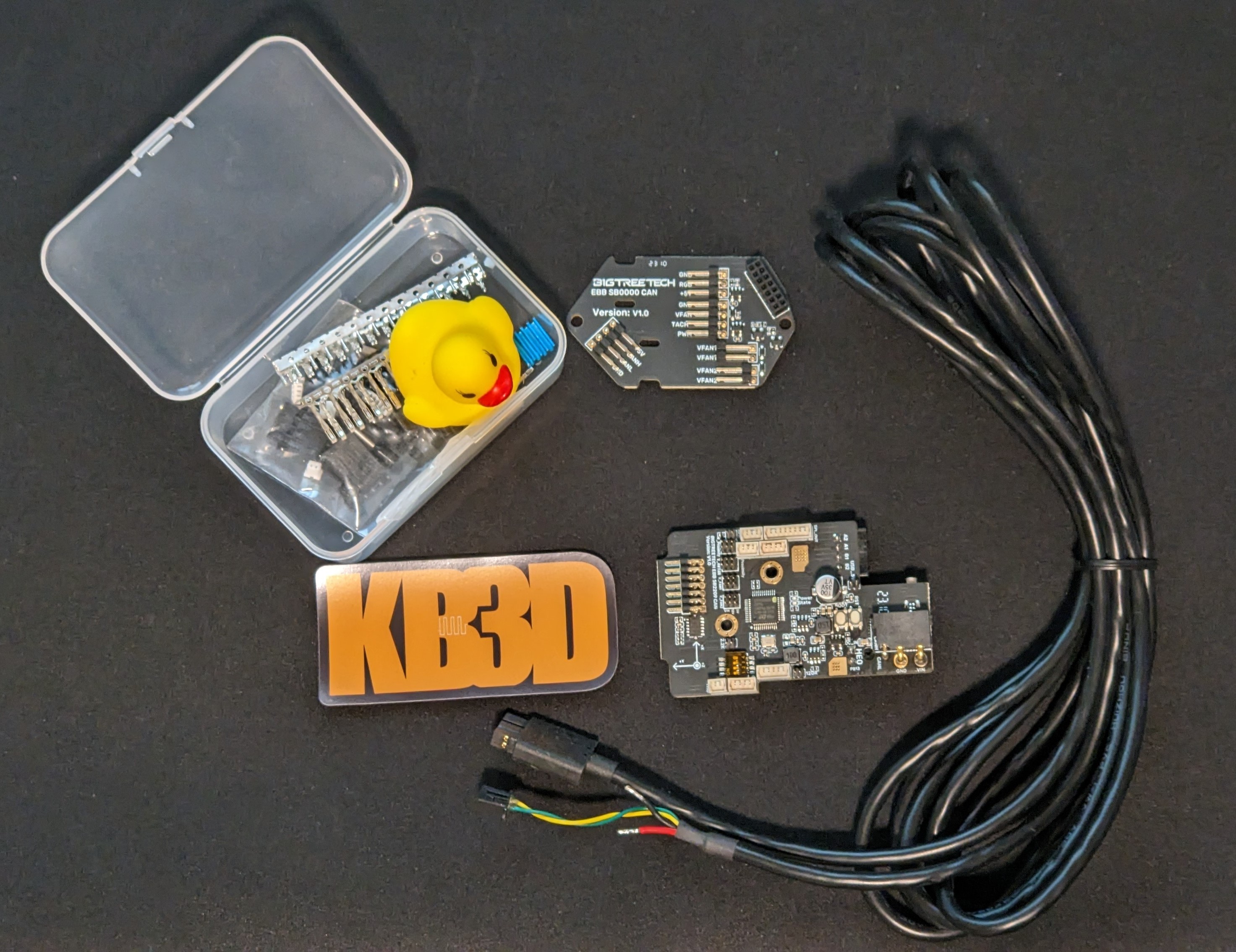
¶ CANbus Wiring
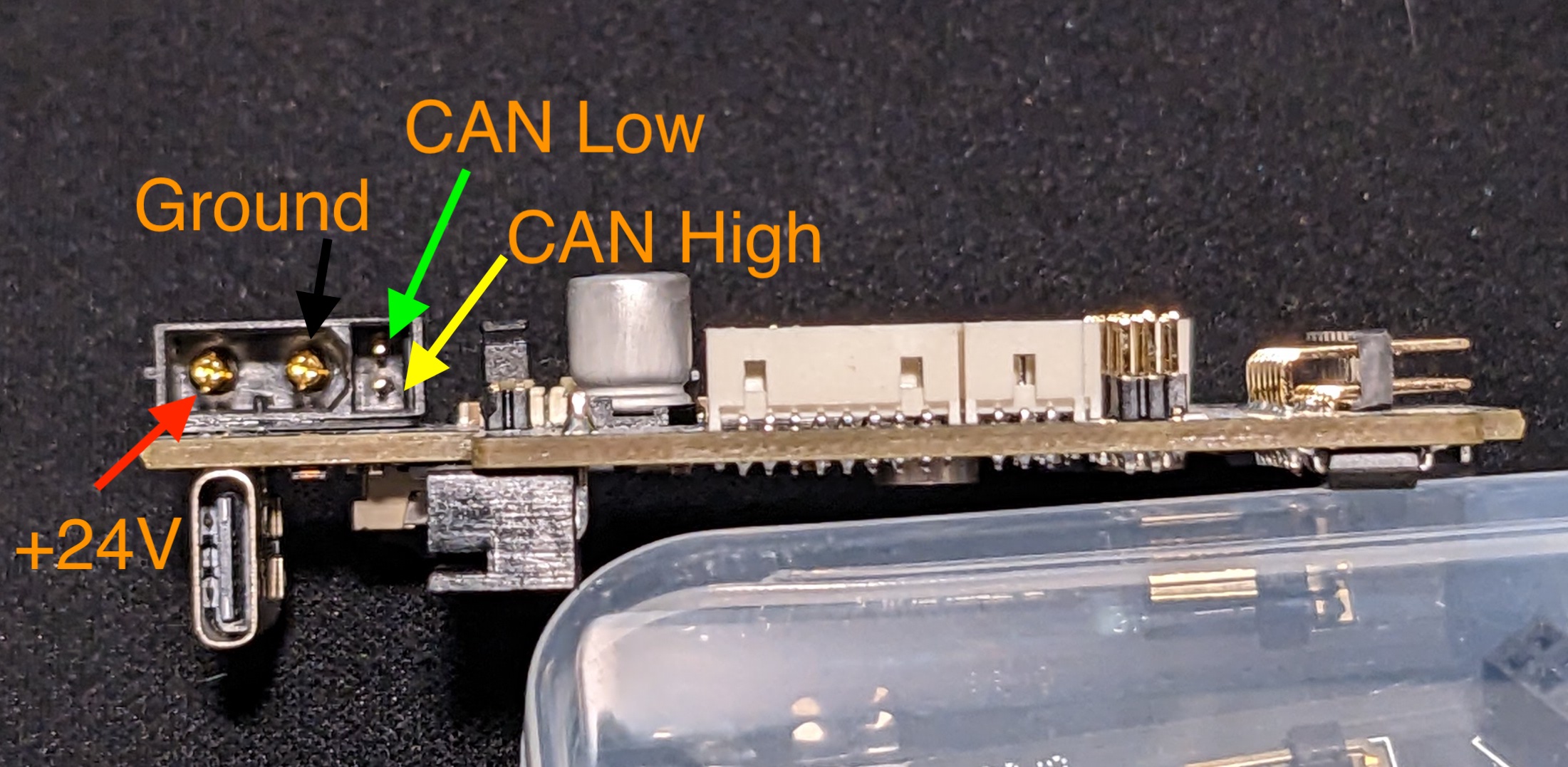
The SB2209 uses a 4pin AMASS XT30 (2+2) connector. Two wires provide the +24v and Ground, the other two are CAN High and CAN Low. The CAN High and CAN Low wires should be 22AWG or 24AWG, but the +24V and Ground should be at least 20AWG. NOTE: Mistakes wiring this connector will likely cause permanent damage to your SB2209.
You can either run your wiring through your existing cable chains, like a normal Voron build, or use an umbillical cable.
¶ Bootloader and Setup
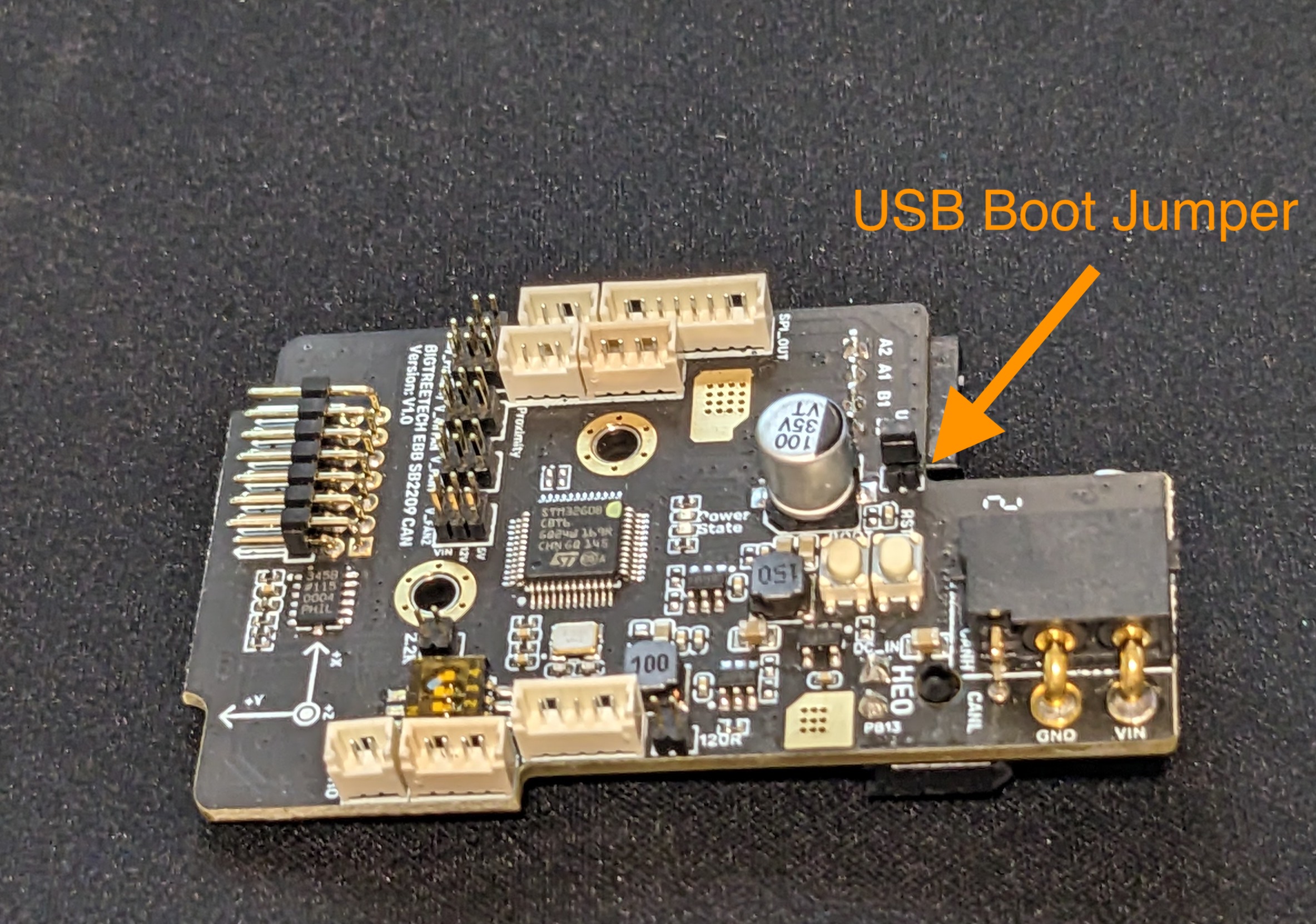
To set up your SB2209, you will first need to plug it into your Raspberry Pi via USB to install CanBoot. Before connecting your board, you will need to install a jumper so that the board will get power from USB.
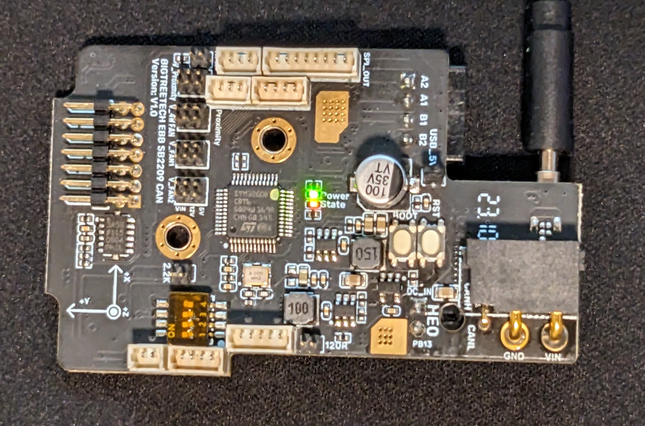
Once it is connected and powered on, you will have both a green and red LED indicators for Power and State.
Now SSH into your Pi, and if you type lsusb, you should see the device.

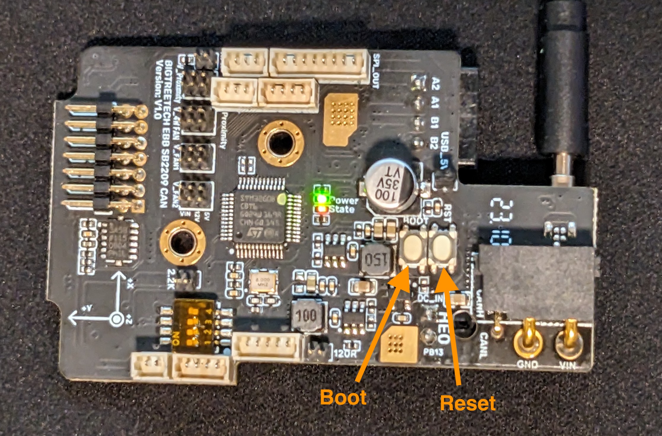
Now that the device is showing up, you need to press and hold the boot button, while clicking the reset button to boot into DFU mode which will allow you to install the CanBoot bootloader. Be careful here and don't use anything metallic or conductive, as the board has power. A toothpick or chopstick work well to press the buttons.
Confirm the board is in DFU mode, by once again using lsusb, note the device has “in DFU mode” after it now.

Once in DFU mode, we need to prepare the CanBoot firmware to install. First we need to download the CanBoot code from Github. This command copies (aka clones) the code from the public repository on GitHub.
pi@hara:~ $ cd ~
pi@hara:~ $ git clone https://github.com/Arksine/CanBoot

Once it is downloaded, you can change into that directory and run make menuconfig. Chose the following options. Ensure the CAN bus speed value matches the configuration on your USB Can Adapter (either BTT U2C or Mellow UtoC). Exit and save the config.

Now you need to compile the bootloader. Run the following commands.
pi@hara:~/CanBoot $ make clean
pi@hara:~/CanBoot $ make
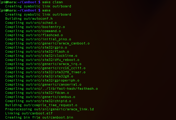
Now that you have created the CanBoot firmware, you need to load it onto the board. You can do that with the following command, as you are using sudo, you will need to enter your password.
sudo dfu-util -a 0 -D ~/CanBoot/out/canboot.bin --dfuse-address 0x08000000:force:mass-erase:leave -d 0483:df11
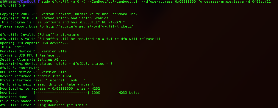
The error at the end is normal, as long an you see File downloaded successfully, you should be good.
At this point, your board is flashed with CanBoot, and you will be able to upload the firmware via CAN in the future. You can unplug your board from the USB cable and connect it to your CAN wiring (to be safe, we recommend powering down your printer to avoid shorting out any electronics).
In almost all cases, you will need to install the jumper to enable the terminating resistor on your SB2209.
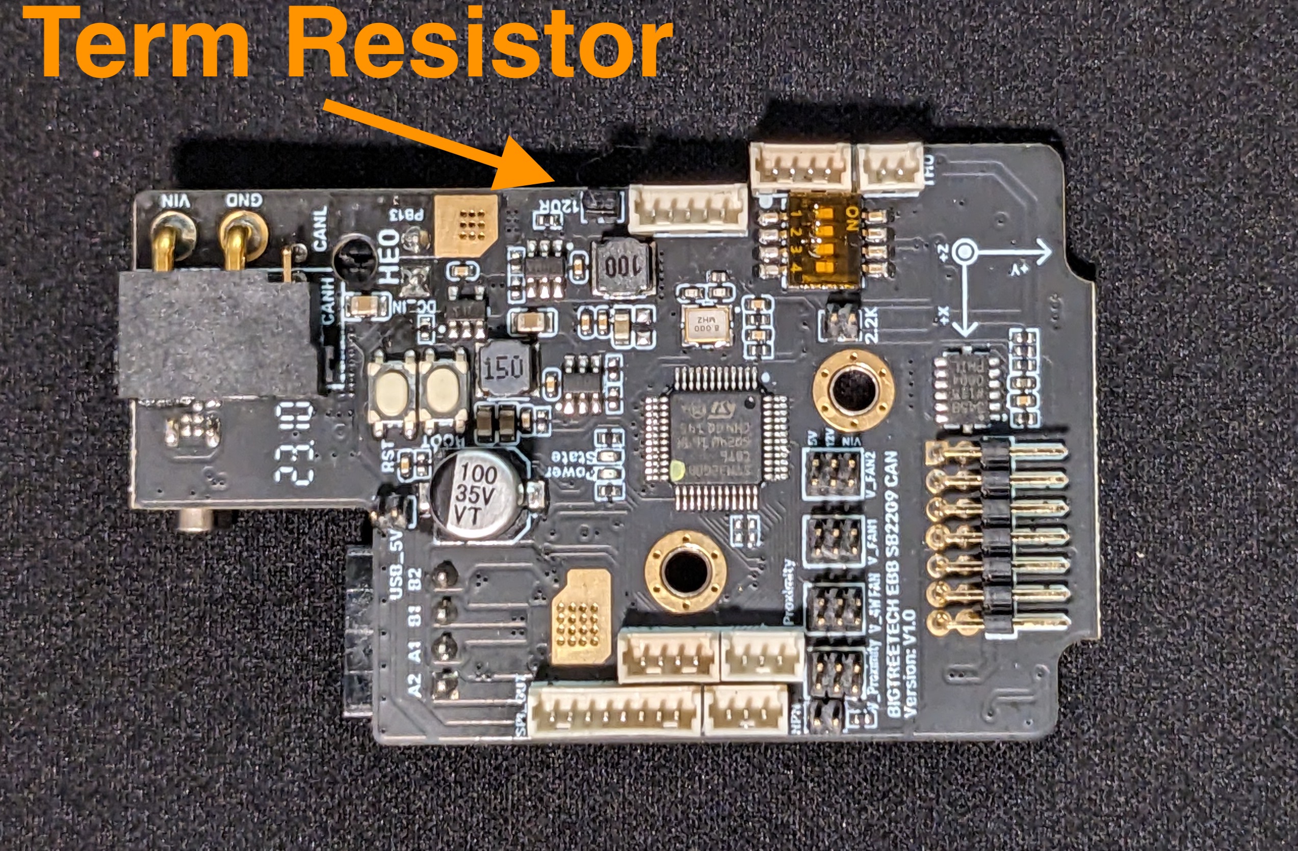
Once you have your SB2209 connected via your CANbus wiring, you should be able to query CANbus and detect the board.
python3 ~/CanBoot/scripts/flash_can.py -i can0 -q

If you do not have any “Detected UUID” lines, then your CAN Adaptor board isn't able to see the SB2209, and you will need to do some troubleshooting.
Once you are able to detect the SB2209 toolhead board, you need to build Klipper to install on it (CanBoot is just the boot loader, which makes installing Klipper easier).
cd ~/klipper
make menuconfigAssuming you have followed these instructions, chose the following options for your SB2209.
DO NOT FOLLOW INSTRUCTIONS PAST HERE, STILL NEED TO UPDATE

Then run make to actually build Klipper, this will take a few minutes.
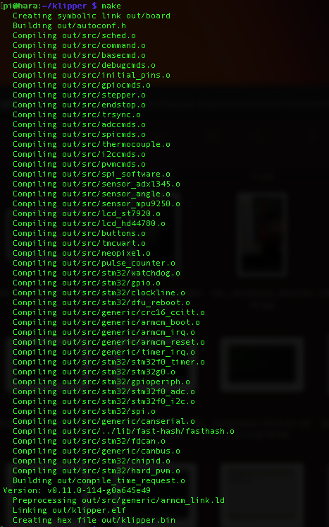
Once that is built you need to flash that to the EBB36. You will need to grab the UUID that was detected earlier, and replace MYUUID in the following command with that.
python3 ~/CanBoot/scripts/flash_can.py -i can0 -u MYUUID -f ~/klipper/out/klipper.bin
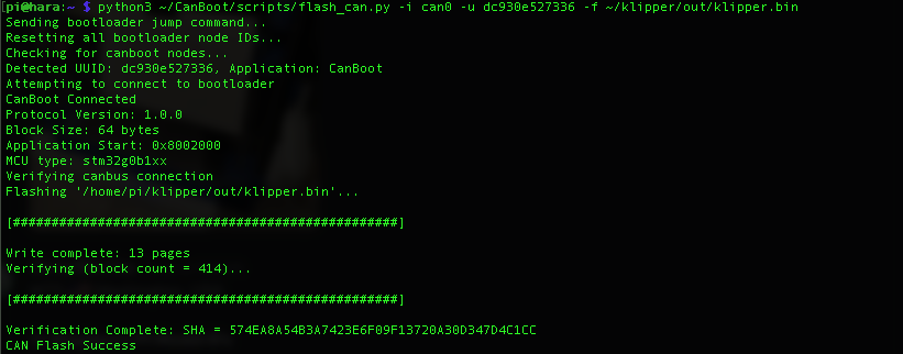
You should see CAN Flash Success at the end. Now you can run the klipper canbus_query command and see the UUID showing that the Application is Klipper.
NOTE: If you get this error [###ERROR:root:Can Read Error You may need to reflash your CAN Adapter (some U2C v2.1 boards had bad firmware installed from the factory). Please read this section of Esoterical's documentation on Github to re-flash your U2C.
~/klippy-env/bin/python ~/klipper/scripts/canbus_query.py can0

Now your EBB36 is all configured and ready to go.
¶ Stealthburner Mounting
The EBB36 is designed to mount behind a 36mm stepper, used on both the Stealthburner and mini-SB/AB toolheads. Depending on how you plan on running the wire to your toolhead, you have a few different options for a mount.
If you are using this with a Stealthburner toolhead and you are going to keep your cable chains, you can use this mounting bracket from nzalog on Printables.
For use with the Stealthburner toolhead using an umbilical cable, we recommend this mounting bracket from Coxie on Printables.
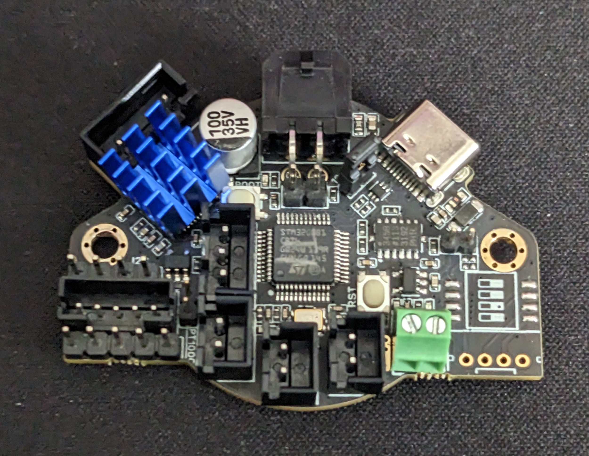
Before mounting your EBB36, make sure you install the Stepper driver heatsink.
¶ Toolhead Wiring
Here is the wiring diagram provided by BTT on their Github page. Note, the wiring diagram and manual are the same between the EBB36 v1.1 and v1.2.
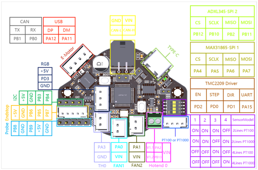
The connectors most people will use are all JST-XH, except for the hot end heater which uses a ferrule and the probe port (endstop in the diagram above) which is JST-PH.
And here is a breakdown of what that all means to you.
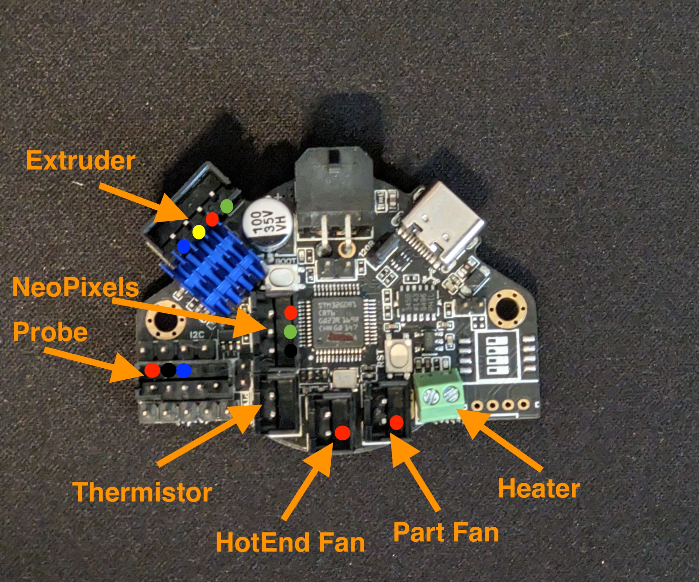
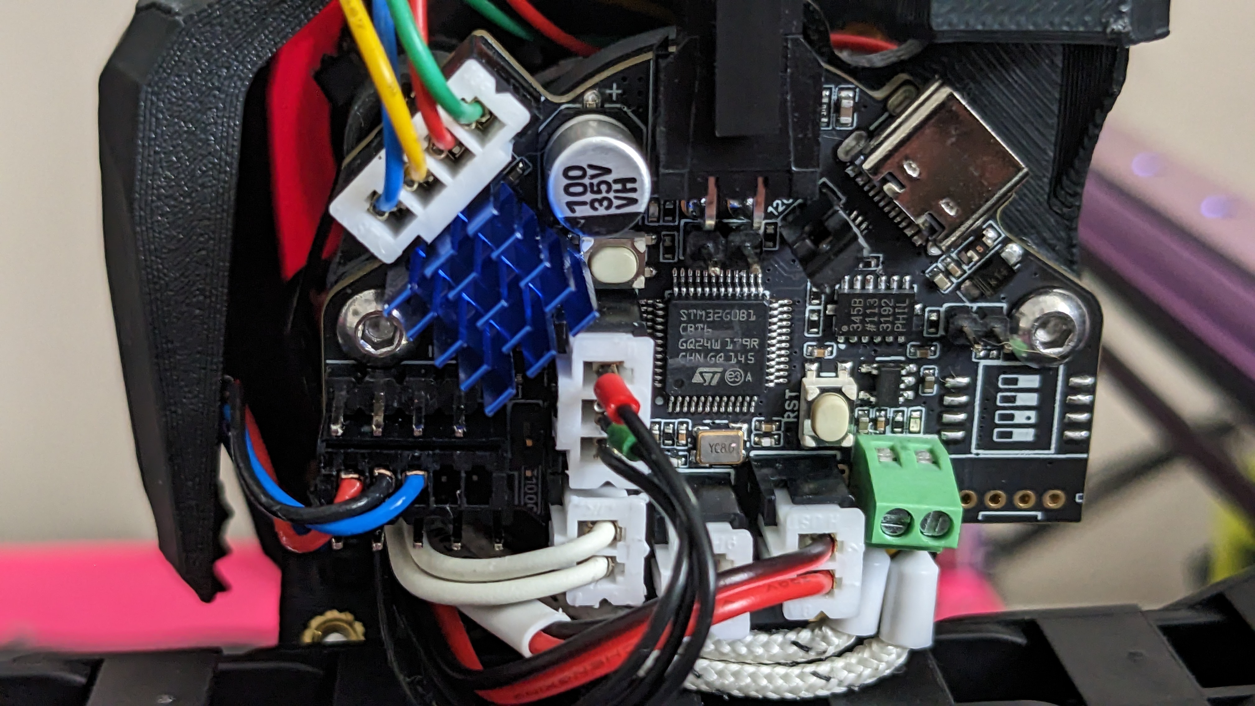
For the Extruder, if you are using the LDO 36STH20-1004AHG, then you can follow the color coding in the picture. For the Neopixels, the top pin is +5v, the middle is signal and the bottom is ground. For your probe, we recommend using the Endstop pins, as JST-PH has a more secure connection that the Dupont used on the probe headers. NOTE: getting +24V is a challenge with the EBB36, so if you are using an Omron style probe, the EBB36 may not be an ideal solution. If you are using Klicky you will only need the ground and signal. If you are using TAP or Euclid, then you can pull +5V from the left most pin, ground from the next pin, and signal on the third pin. The remaining pins aren't used. The remaining wiring for your toolhead is pretty self explanatory. Here is a completed board with wiring for reference.
¶ Printer Configuration
Once you have wired everything, and confirmed you are connecting to the EBB36 via CANbus, you will then need to update your printer config. You will get an MCU error, until you have updated a few things.
First you need to add the EBB36 as another MCU, you will need the UUID from before,
python3 ~/CanBoot/scripts/flash_can.py -i can0 -q

In your printer.cfg file, you can add this line, after the [mcu] section. Replace MYUUID with the UUID detected above.
[mcu EBBCan]
canbus_uuid: MYUUID 
The next thing to update is your hotend thermistor, but while we are in the [extruder] section, we might as well update everything. You will need to update the following lines..
step_pin: EBBCan:PD0
dir_pin: !EBBCan:PD1
enable_pin: !EBBCan:PD2

heater_pin: EBBCan: PB13
sensor_pin: EBBCan: PA3
In the [tmc2209 extruder] section just below, you need to change
uart_pin: EBBCan: PA15At this point, you should be able to save and restart, and Klipper should start normally. To confirm the EBB36 is communicating properly, you should see it listed on the Machine panel, under system loads.

Now you can go back into your printer.cfg and update the remaining items in each section listed below.
[probe]
pin: EBBCan:PB6

##  Part Cooling Fan - FAN0
[fan]
pin: EBBCan: PA1

##  Hotend Fan - FAN1
[heater_fan hotend_fan]
pin: EBBCan:PA0

[neopixel sb_leds]
pin: EBBCan:PD3
You can add this section to monitor the temp on the EBB36.
[temperature_sensor EBBCan]
sensor_type: temperature_mcu
sensor_mcu: EBBCan
min_temp: 0
max_temp: 100
And to utilize the ADXL chip on the EBB36, you can add this. NOTE: Change the probe_points values to the appropriate value for your printer, for a 350mm v2.4, they would be 175,175,20. Here is a link to the Klipper docs on Input shaper.
[adxl345]
cs_pin: EBBCan:PB12
spi_software_sclk_pin: EBBCan:PB10
spi_software_mosi_pin: EBBCan:PB11
spi_software_miso_pin: EBBCan:PB2
axes_map: x,y,z

[resonance_tester]
accel_chip: adxl345
probe_points: X,Y,Z
That should be everything that needs to be updated in your printer.cfg. You will need to save and restart, but that should complete your CANbus setup.