¶ Voron Tap OptoTap PCB by Linneo
For the most current information (including assembly instructions) see the Voron Github.
!!!!!! WARNING !!!!!
The Voron Development team has found an issue with the OptoTap v2.1 PCB (24V). In-rush current from the PSU can exceed the capabilities of the voltage regulator, causing it to blow. At this time the safest option is to run both v1.0 and v2.1 OptoTAP PCB's at 5V. A new design has been finalized, but due to the shortage of the optical sensor, production of the new boards is expected to take a month or two. This page will be updated when the new version is available.
OptoTap v1.0 was designed for use with 5 volt inputs most typically coming from a carriage mounted CAN board or directly from the controller. Many controllers have a 5V source as part of the end stop circuits. The V1.0 Tap PCB comes pre-soldered with a length of wire terminated in a Molex Microfit 3.0 receptacle. For plug and play operation you can use an extension harness from Linneo. You are also able to modify the Linneo Stealthburner Toolhead board and the 2 piece Stealthburner Toolhead boards to provide 5v for your sensor.
¶ Stealthburner Toolhead Board (1 piece)
Their are two options to provide 5v to the OptoTap sensor.
1) Following hartk's instructions, you can cut two traces on the front of the board, and then solder two short jumper wires to the back. Due to the JST connectors on the front of the board, it is fairly difficult to get access to cut these traces. It may be possible to gently remove the JST plastic header for the filament sensor to gain access, but the second option is likely easier.
2) The second option is to pull 5V from the 14pin Molex connector solder pin on the back. You will need to connect the red wire from your OptoTap v1.0 sensor to the 5v pin on the Molex connector.
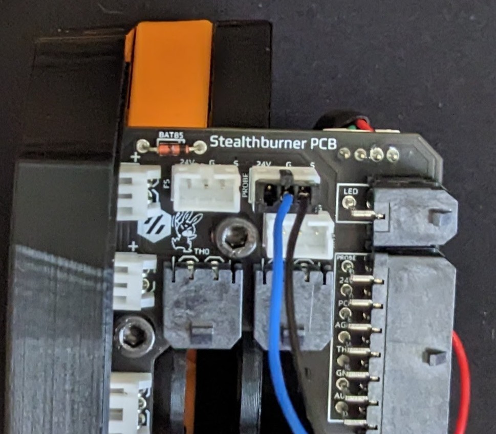
Then you can simply connect the Signal and Ground wires to the PROBE port. NOTE, these wires are colored differently than expected , Blue is Ground and Black is Signal.
¶ Stealthburner 2 Piece Toolhead Board
Again, their are two options to provide 5v to the OptoTap sensor.
1 ) Following hark's instructions, you can cut one trace on the back, then solder a short jumper to provide 5v to the FS sensor port, to be used for TAP. Going this route with the 2 Piece board is fairly simple, as the trace and wiring is all easily accessible on the back. Carefully cut the trace.
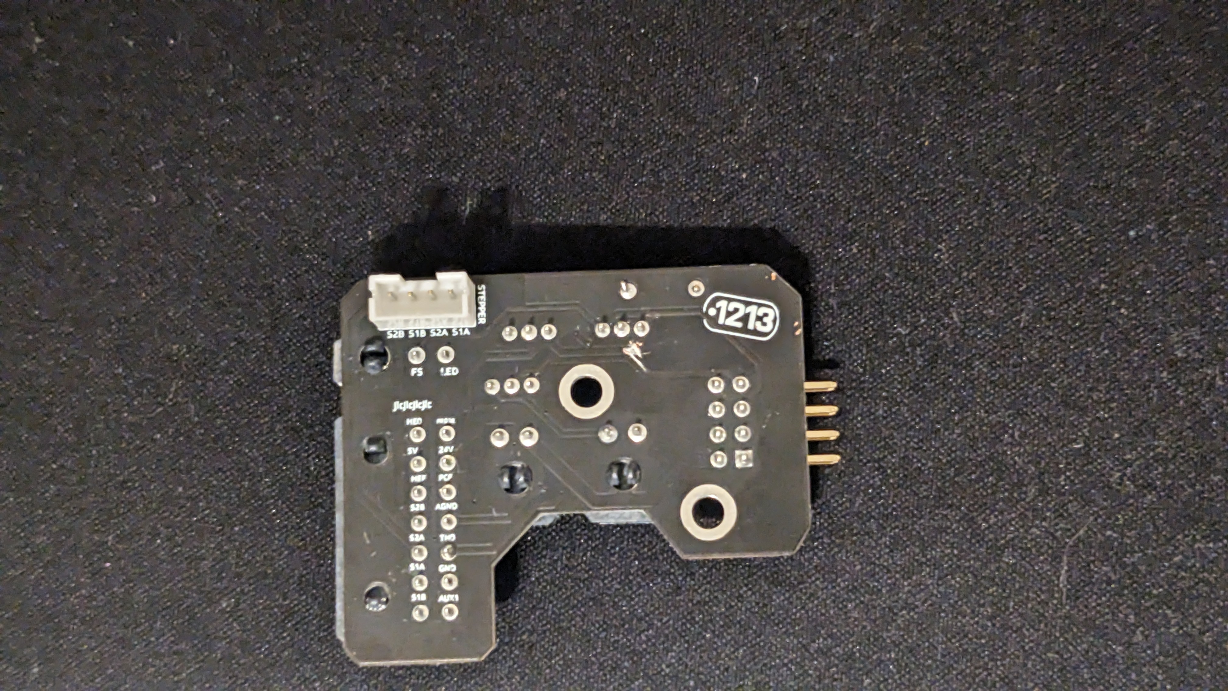
Once the trace is cut, ensure it is cut by measuring for continuity/resistance between the pin and the 24v pin on the 14-pin Molex connector.
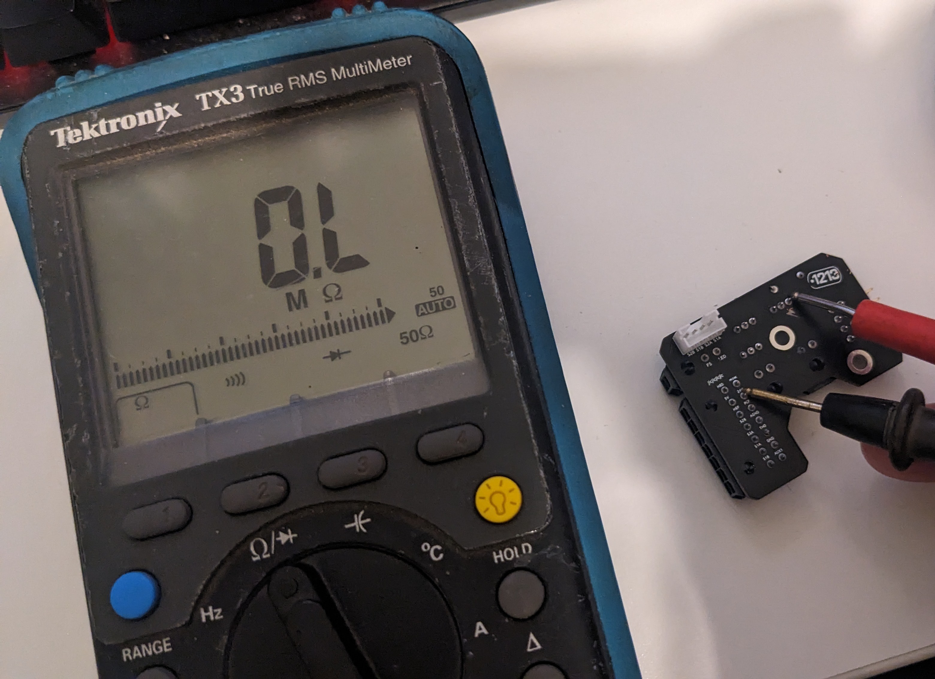
Once you have ensured no connectivity, cut a 16mm wire, strip a small amount off each end and tin the ends. Then solder it to the far right pin on the FS jumper and the 5V to the front SB Board.
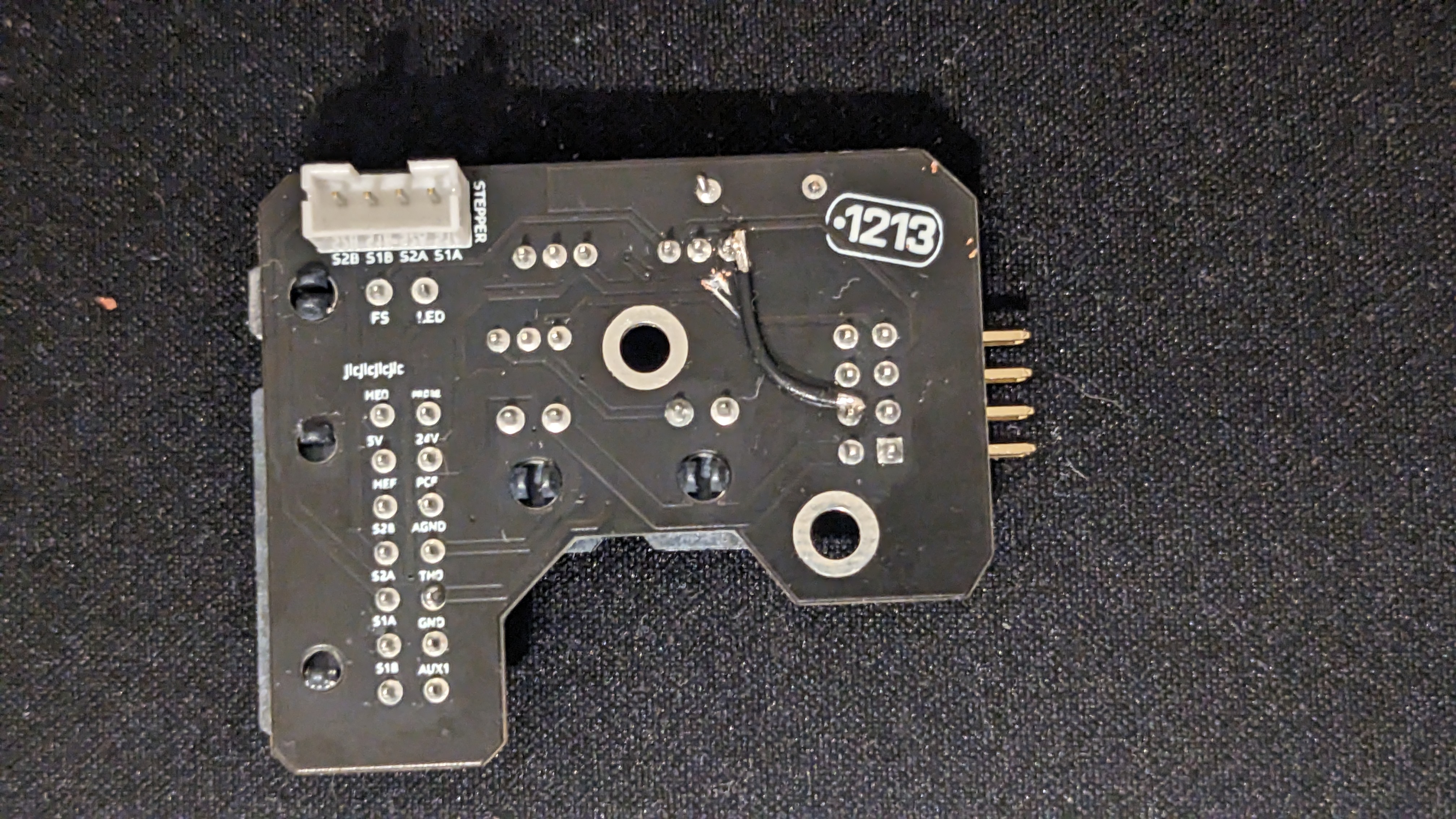
Now you are able to use the FS port for TAP. Make sure you connect the FS wire at the MCU side to the appropriate port, on an Octopus 1.1, that would typically be the outside pin on DIAG7 (PG15).
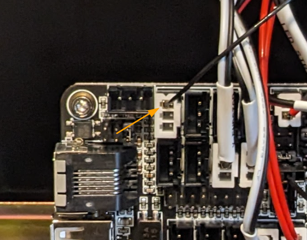
Your wiring should now be done, so you can continue to follow the Voron TAP Klipper instructions.
2) The Second option is to instead pull 5v from the front header feeding the Neopixel.
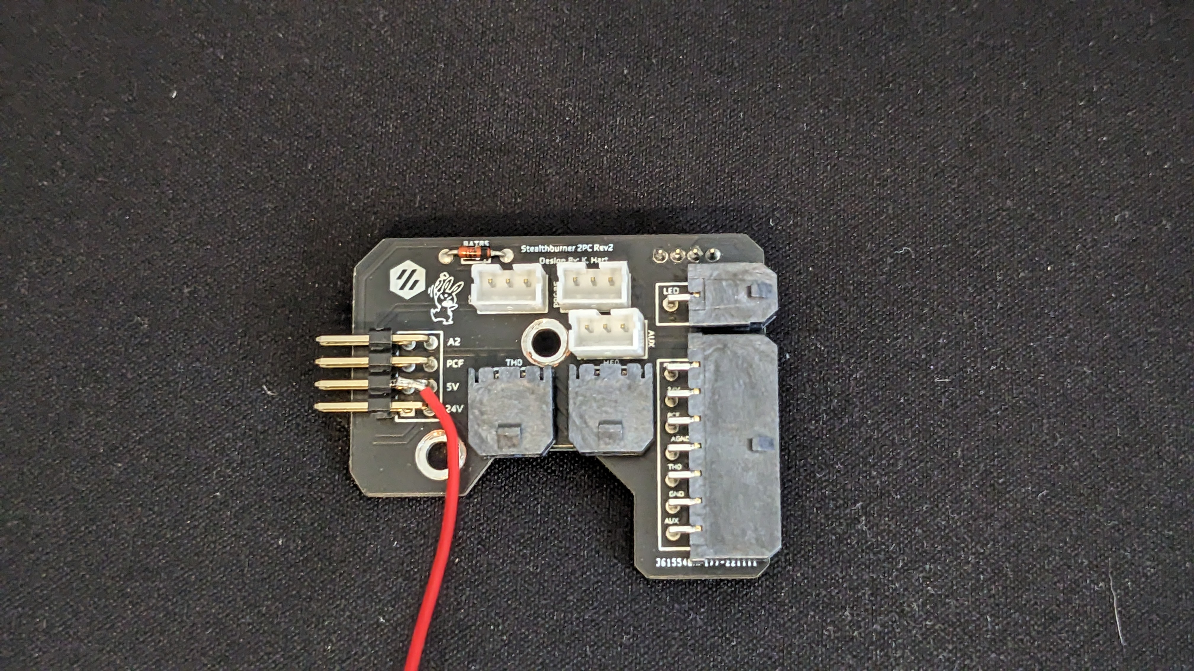
Then you can simply connect the Signal and Ground wires to the PROBE port. NOTE, these wires are colored differently than expected , Blue is Ground and Black is Signal.
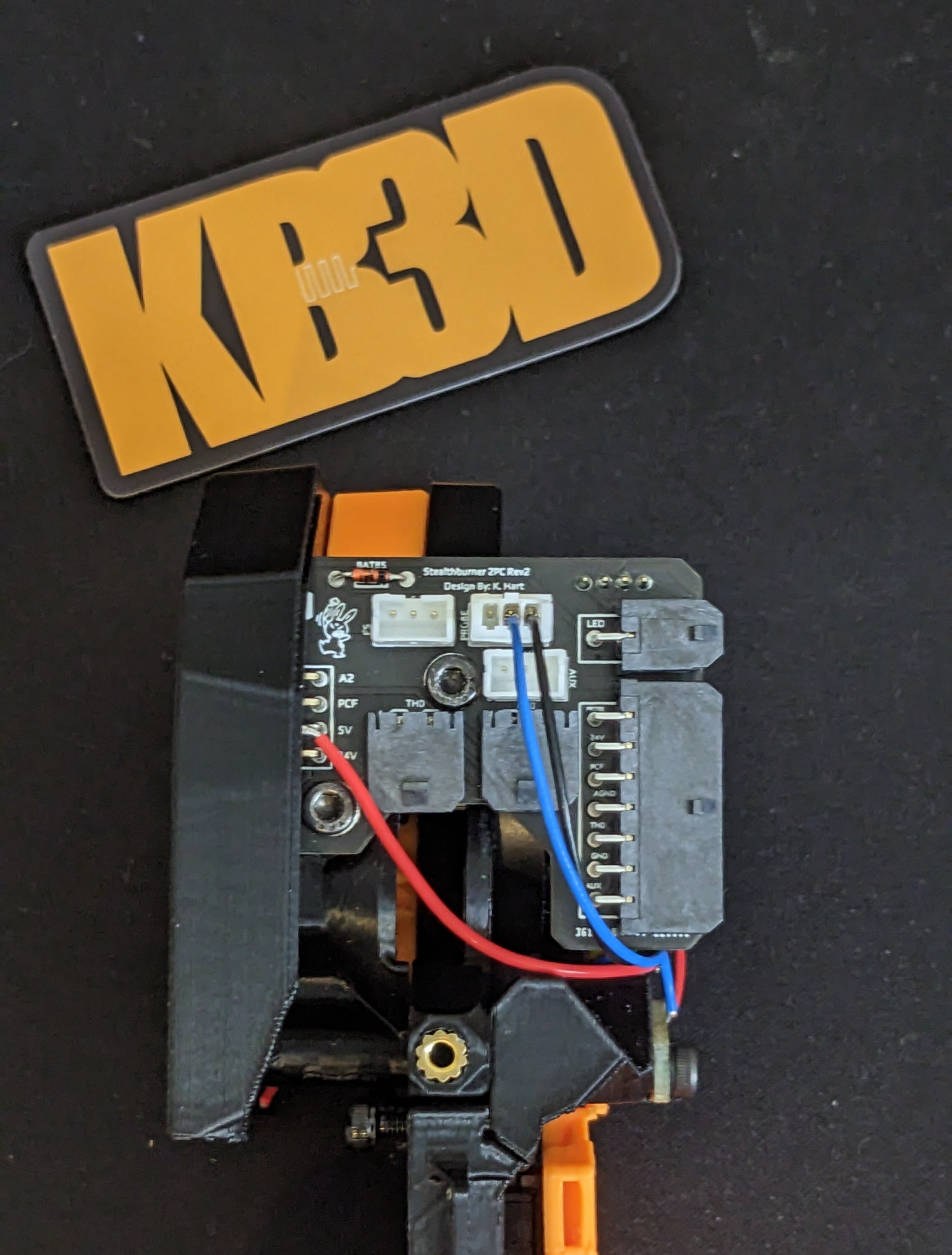
If you are coming from Klicky, you should be done, just confirm the port that you used for klicky before moving on to the software configuration using the Voron TAP Klipper instructions.
If you were using an inductive probe, you can leave your probe signal wire in DIAG7, but remove the two wires going to the Probe port (J40). Your wiring should be as follows.

Your wiring should now be done, so you can continue to follow the Voron TAP Klipper instructions.
¶ Wiring Reference
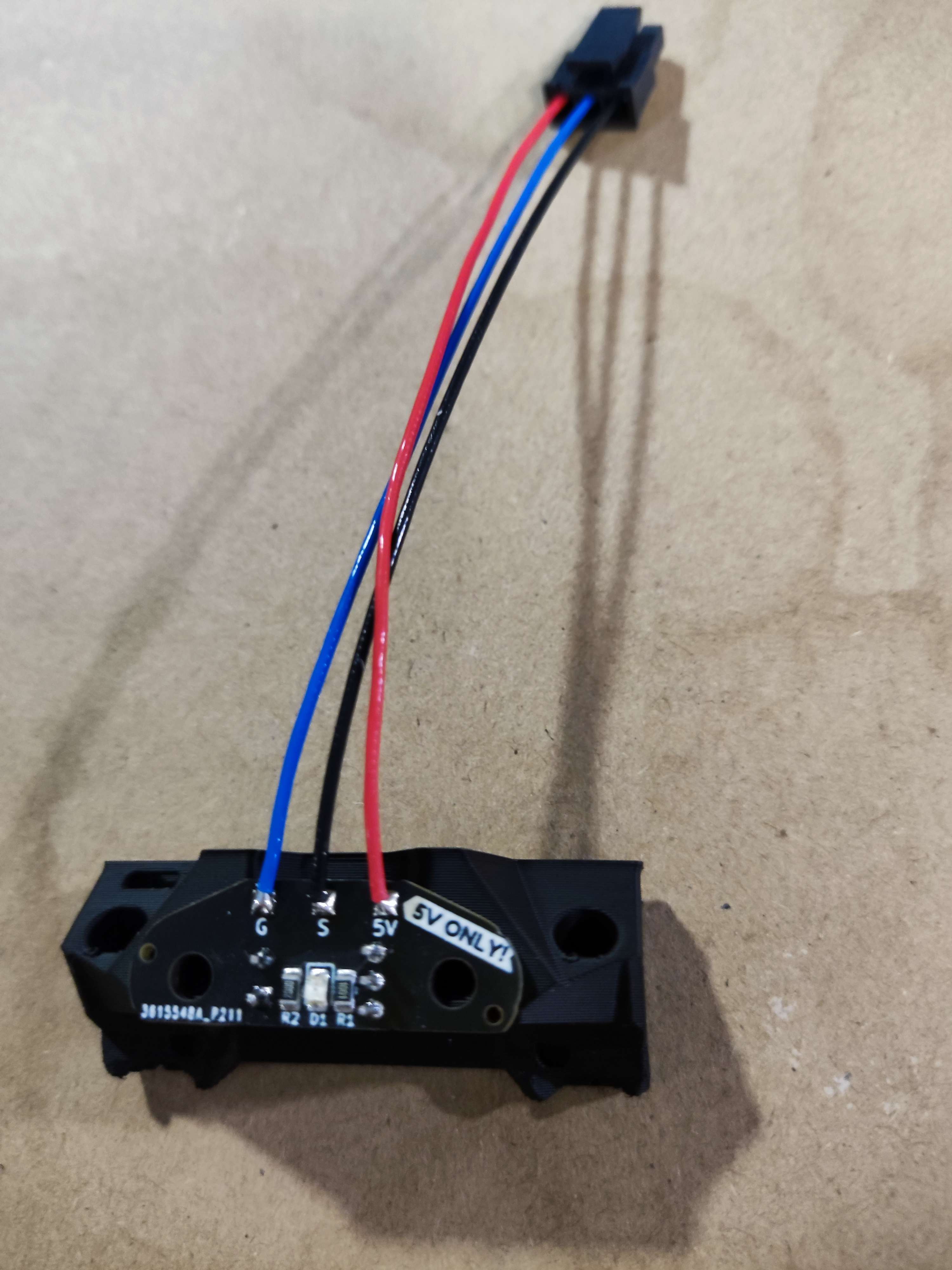
For reference, the wiring of the OptoTAP 1.0 board is as follows.
Red = 5V In
Blue = GND
Black = Switching Trigger Signal
¶ v2.1
IMPORTANT! This harness is directional for trouble-free installation. The direction of the harness is indicated by the color of the JST connectors.
Black = Connect to the Toolhead PCB
White = Connect to the OptoTap V2.1 PCB
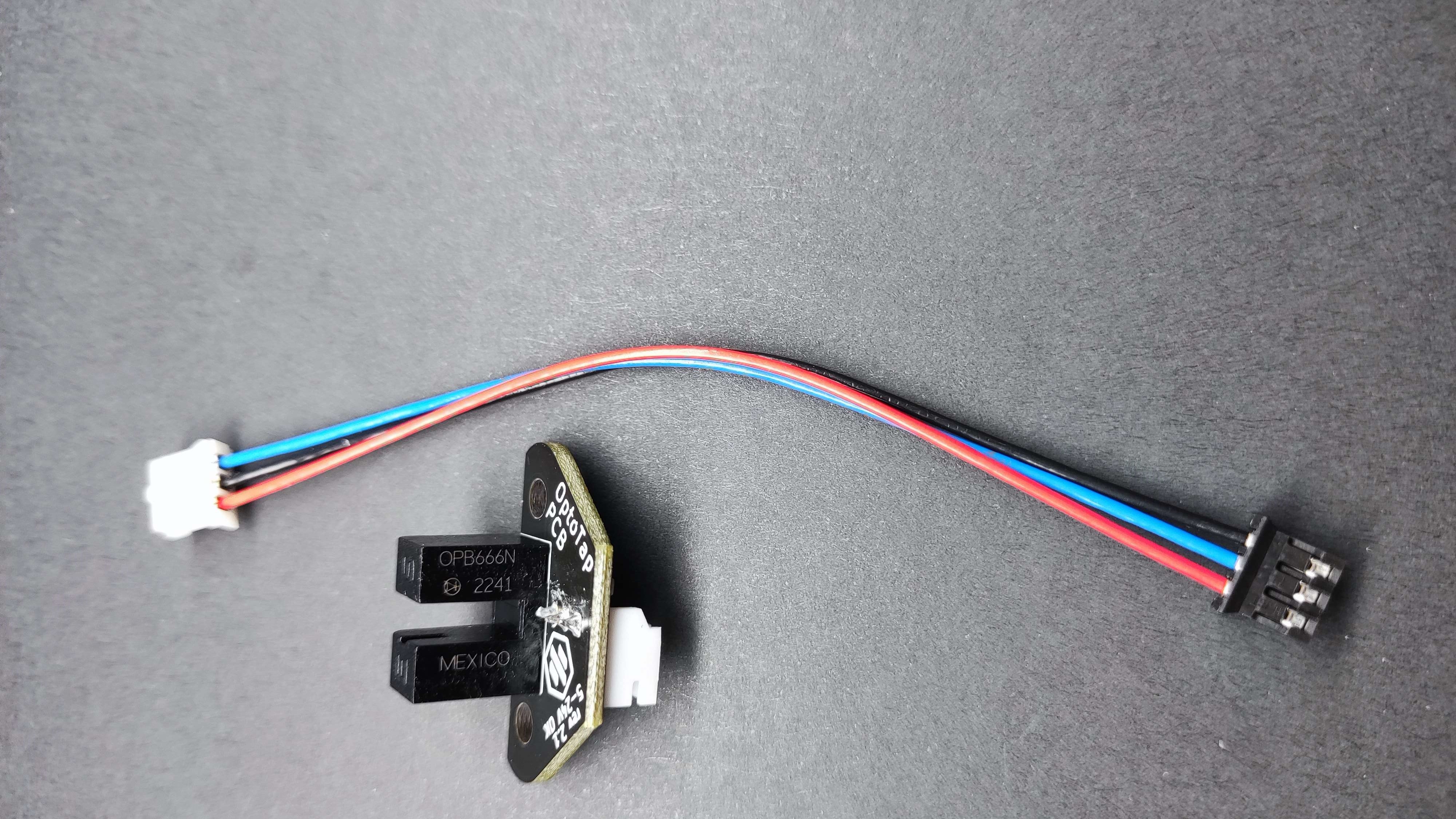
You are able to modify the Linneo Stealthburner Toolhead board and the 2 piece Stealthburner Toolhead boards to provide 5v for your sensor.
Stealthburner Toolhead Board (1 piece)
Their are two options to provide 5v to the OptoTap sensor.
1) Following hartk's instructions, you can cut two traces on the front of the board, and then solder two short jumper wires to the back. Due to the JST connectors on the front of the board, it is fairly difficult to get access to cut these traces. It may be possible to gently remove the JST plastic header for the filament sensor to gain access, but the second option is likely easier.
2) The second option is to pull 5V from the 14pin Molex connector pin on the back. You will need to de-pin the the red wire on the wiring harness, cut off the pin and trim back a small amount of wire. Then tin the wire with some solder and solder it to the 5V pin on the 14-pin Molex.
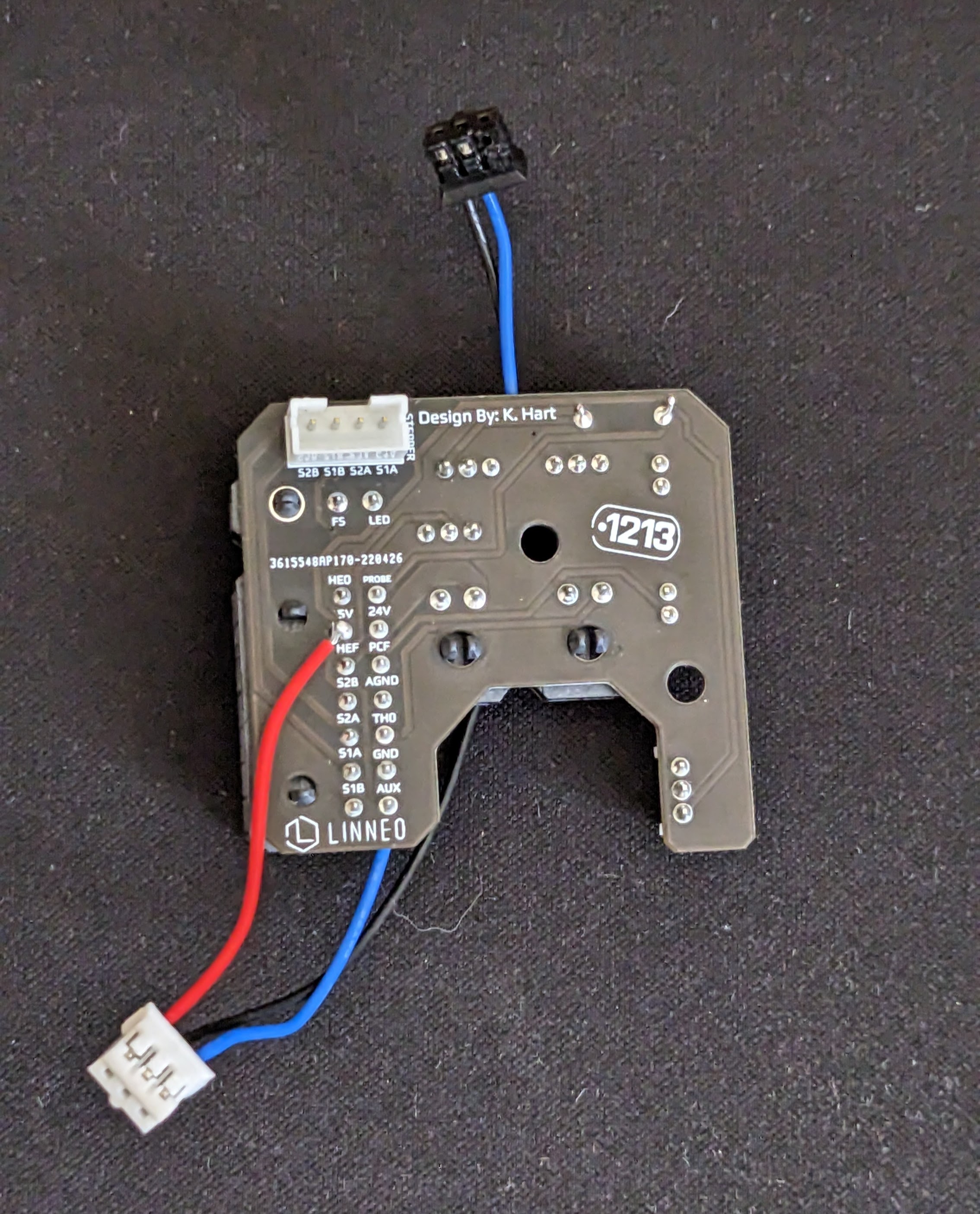
Ensure the solder joint doesn't stick out too far, as the back of the PCB is fairly close to the extruder stepper motor.
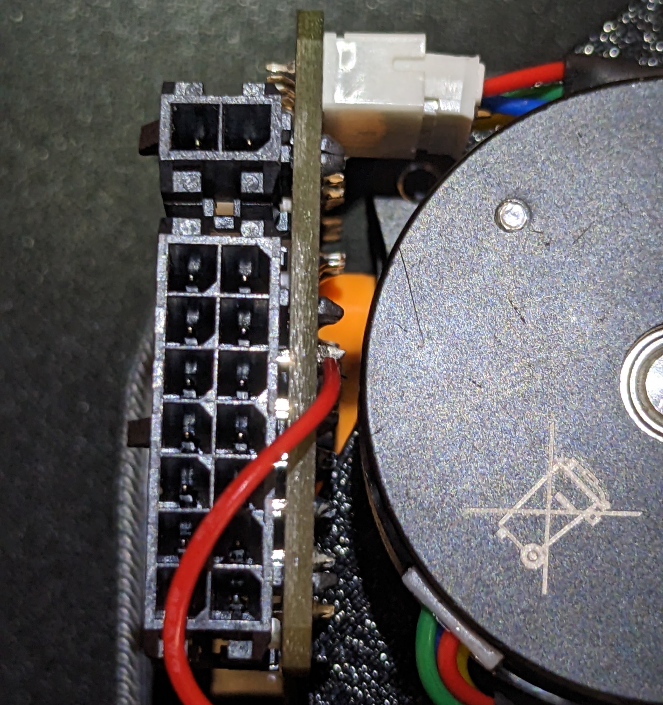
And that is all you need to do for the wiring.
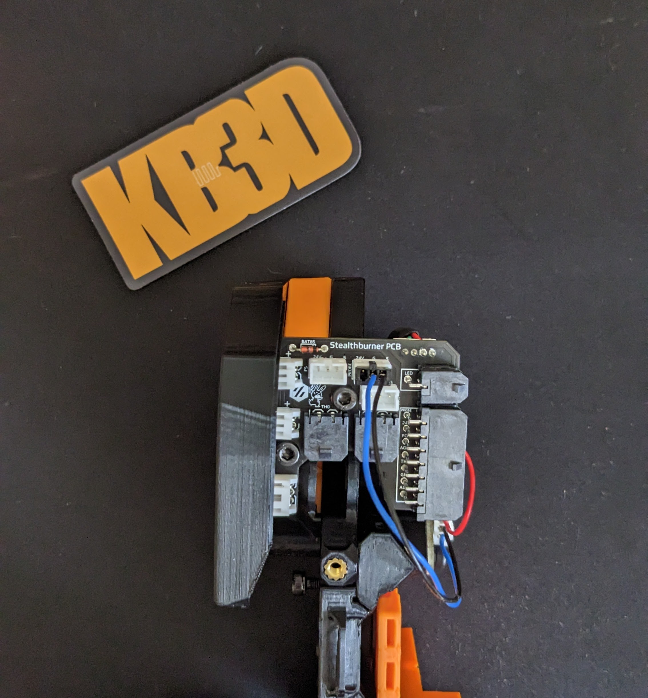
If you are coming from Klicky, you should be done, just confirm the port that you used for klicky before moving on to the software configuration using the Voron TAP Klipper instructions.
If you were using an inductive probe, you can leave your probe signal wire in DIAG7, but remove the two wires going to the Probe port (J40). Your wiring should be as follows.

Your wiring should now be done, so you can continue to follow the Voron TAP Klipper instructions.
¶ Stealthburner 2 Piece Toolhead Board
Again, their are two options to provide 5v to the OptoTap sensor.
1 ) Following hark's instructions, you can cut one trace on the back, then solder a short jumper to provide 5v to the FS sensor port, to be used for TAP. Going this route with the 2 Piece board is fairly simple, as the trace and wiring is all easily accessible on the back. Carefully cut the trace.

Once the trace is cut, ensure it is cut by measuring for continuity/resistance between the pin and the 24v pin on the 14-pin Molex connector.

Once you have ensured no connectivity, cut a 16mm wire, strip a small amount off each end and tin the ends. Then solder it to the far right pin on the FS jumper and the 5V to the front SB Board.

Now you are able to use the FS port for TAP. Make sure you connect the FS wire at the MCU side to the appropriate port, on an Octopus 1.1, that would typically be the outside port on DIAG7 (PG15).

Your wiring should now be done, so you can continue to follow the Voron TAP Klipper instructions.
2) The Second option is to instead pull 5v from the front header feeding the Neopixel.

Then you can simply connect the Signal and Ground wires to the PROBE port. NOTE, these wires are colored differently than expected , Blue is Ground and Black is Signal.
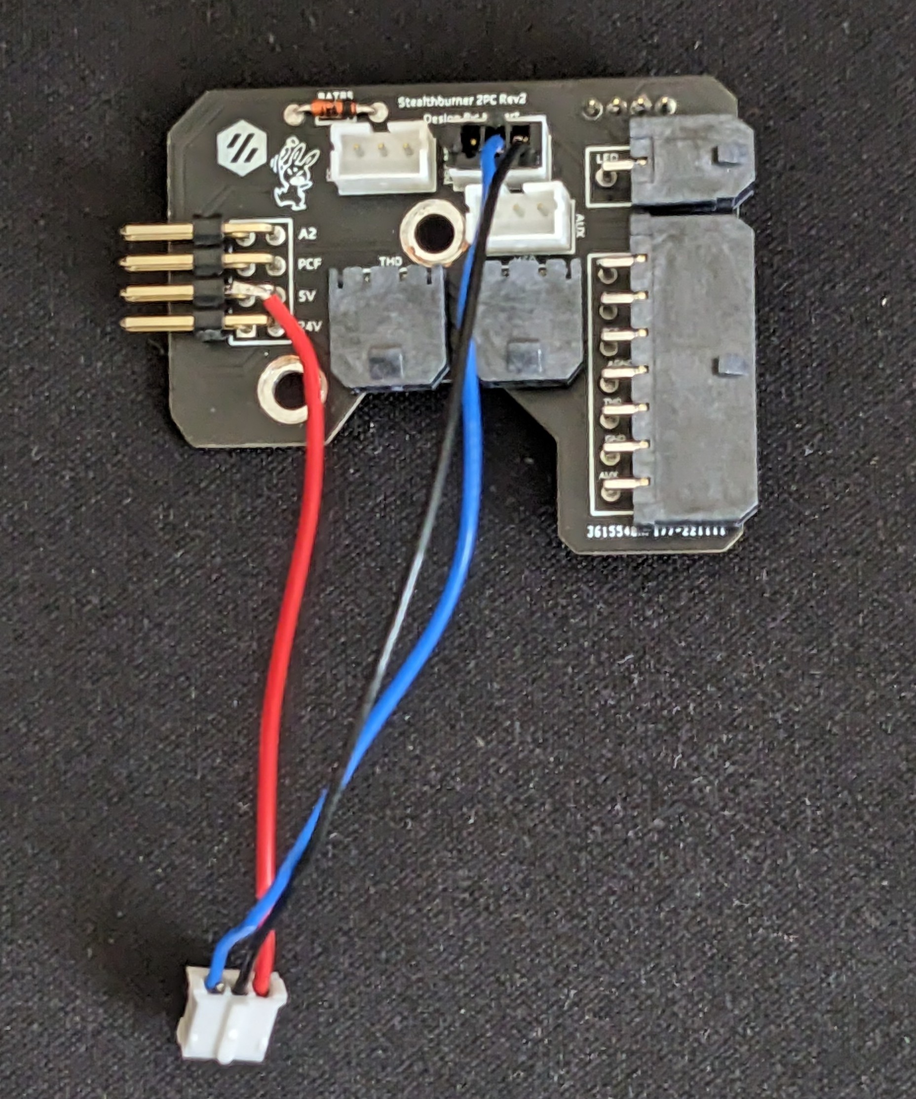
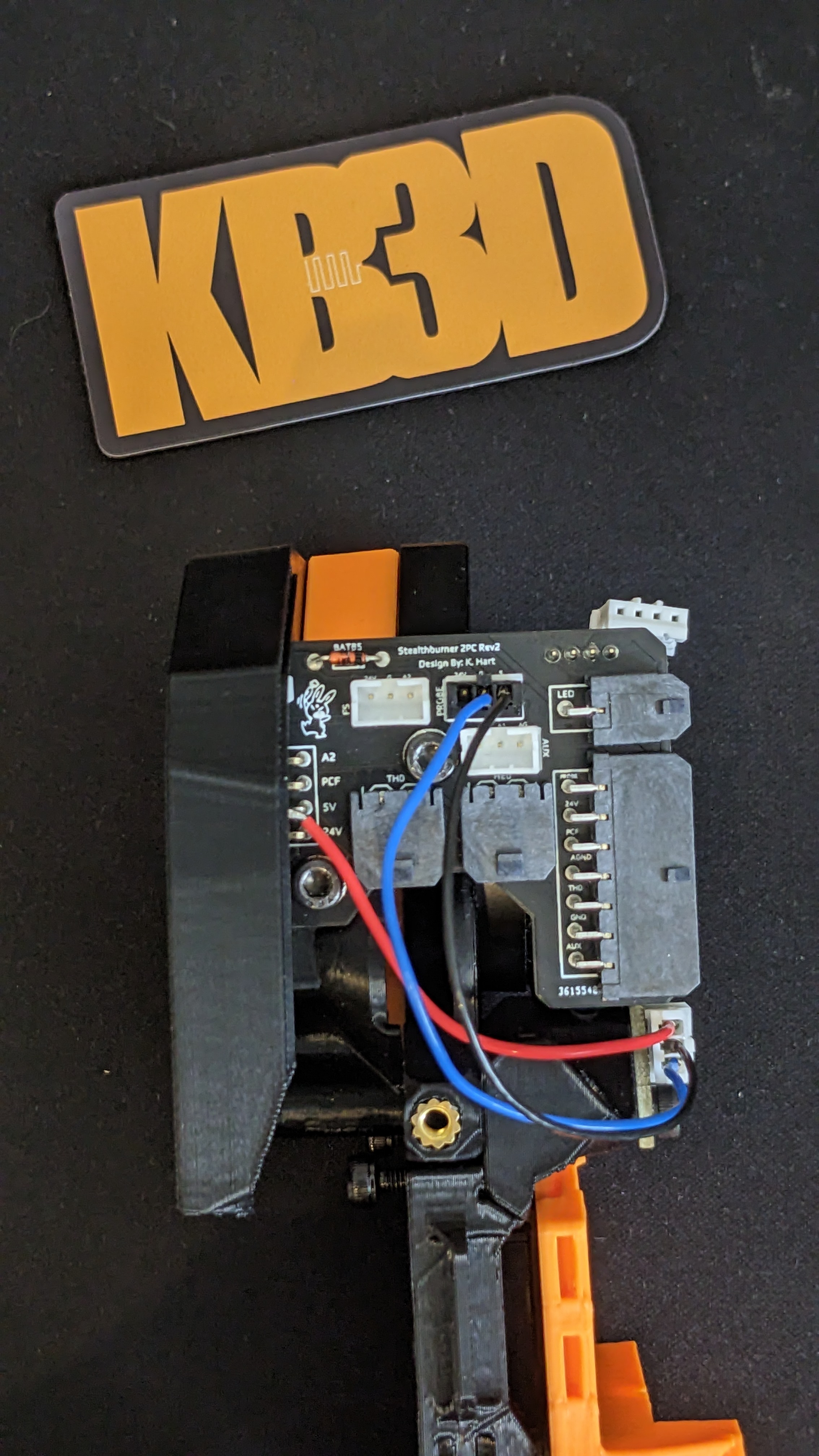
If you are coming from Klicky, you should be done, just confirm the port that you used for klicky before moving on to the software configuration using the Voron TAP Klipper instructions.
If you were using an inductive probe, you can leave your probe signal wire in DIAG7, but remove the two wires going to the Probe port (J40). Your wiring should be as follows.

Your wiring should now be done, so you can continue to follow the Voron TAP Klipper instructions.
¶ Directly Wired
If you are not running a Stealthburner Toolhead board, you can reuse your existing wires, but ensure you update your wiring to pull 5V and Ground from a Fan header set to 5v.
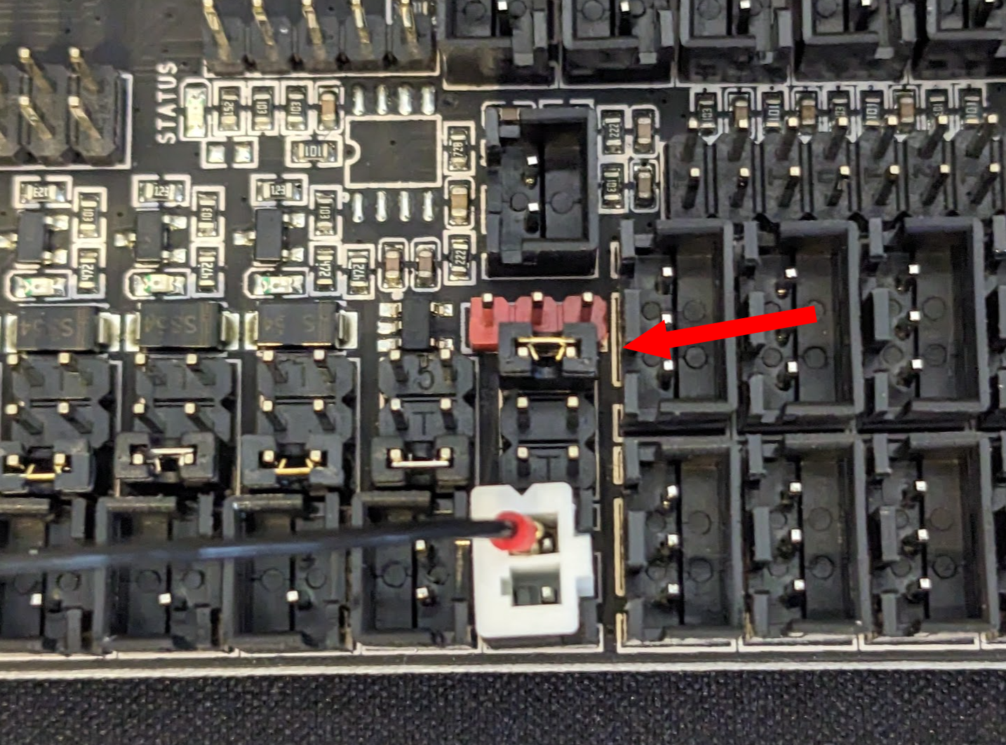
And then connect the signal wire from TAP to the DIAG7 signal wire (PG15)

Once you are done wiring, you can follow the Voron TAP Klipper instructions.
¶ Wire color assignments (for reference):
Red = 5V In
Blue = GND
Black = Switching Trigger Signal