¶ Rainbow Barf LED Harness Installation Tips
¶ For Linneo Pre-soldered variants
The color coding for the pre-terminated wiring is as follows:
Red - +5V
Green - Neopixel Signal
Black - Ground
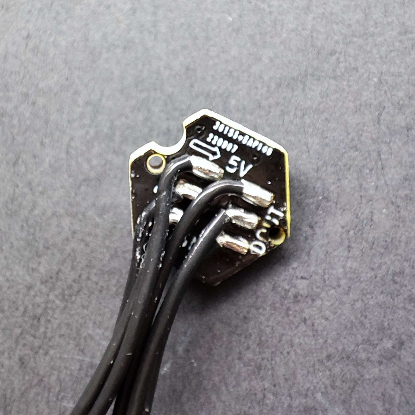
1. Your Harnesses wires are not soldered in the wrong direction!
2. During insertion into the printed part we will bend the wires 90 degrees as shown.
Link to printed part here

a. When bending the wires, try to bend them as far from the soldering pad as possible. Bending the wire too sharply near the pads can cause damage!
4. Add the following to your printer.cfg file:
[neopixel sb_leds]
pin: PB0
# The pin connected to the neopixel. This parameter must be provided.
chain_count: 10
# 8 Rainbow barf + 2 Toolhead
# The number of Neopixel chips that are "daisy chained" to the
# provided pin. The default is 1 (which indicates only a single
# Neopixel is connected to the pin).
color_order: GRB,GRB,GRB,GRB,GRB,GRB,GRB,GRB,GRBW,GRBW
# Set the pixel order required by the LED hardware. Options are GRB,
# RGB, GRBW, or RGBW. The default is GRB.
initial_RED: 1.0
initial_GREEN: 0.45
initial_BLUE: 0.0
initial_WHITE: 0.0
# Sets the initial LED color of the Neopixel. Each value should be
# between 0.0 and 1.0. The WHITE option is only available on RGBW
# LEDs. The default for each color is 0.#Note, the pin in this example configuration is for an Octopus 1.1 MCU, other controller boards may differ, update the pin assignment accordingly.
Known PIN ID's:
Leviathan V1.2: PF10
SKR1.4 pin: 1.24
BTT Octopus: pin: PB0
Troubleshooting
If you run into any issue with your Neopixel’s, you can test each LED with the following commands at the console.
First, turn off each of the lights.
SET_LED LED="sb_leds" RED=0 GREEN=0 BLUE=0 SYNC=0 TRANSMIT=1
Then test each LED with the following.
SET_LED LED="sb_leds" RED=1 GREEN=0 BLUE=0 WHITE=0 TRANSMIT=1 index=1
Increment the index= value until you have tested each LED.
In some cases, installing a 100ohm resistor in-line with the signal wire very close to the motherboard can resolve some color related issues.
Need help? Contact us anytime!