¶ Linneo Under The Deck Wiring Guide.
This is a guide to help assist builders with the Linneo Under The Deck Wiring Kit.
In this guide we will be using the Kit that can be found here:
Linneo Under The Deck Wiring Kit
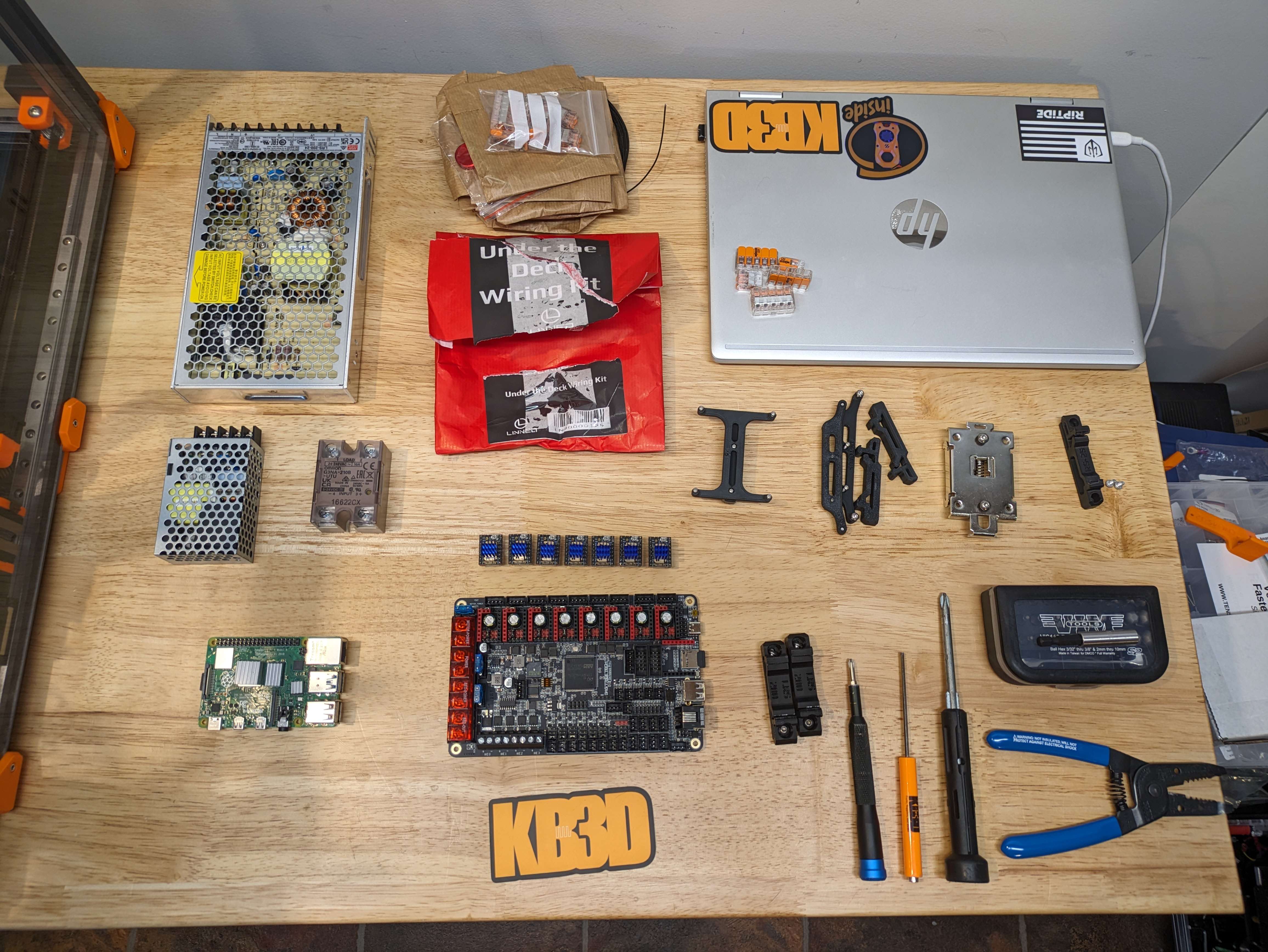
We will first want to gather all of the parts that are going to use in the installation of the lower deck wiring of the machine, these will be the following items.
- 24V Meanwell Power Supply.
- 5V Meanwell Power Supply.
- SSR
- SSR Din Rail Mount
- Raspberry Pi of Choosing, We are using a Pi 4 4GB for this install.
- Controller Board of Choice, We will be utilizing the BTT Octopus Pro & Steppers
- 3D Printed mounts for PSU’s, PI, and Controller board. All can be found Voron Github Electronics Bay Repo
- Linneo Under The Deck Wiring Kit
- Tools,
- I used a ball hex kit that I had, but you will need a 2mm, 2.5mm and 3mm Hex head tool.
- A Smaller Phillips head screw driver,
- Larger phillips head screw driver.
- Wire Strippers
- Wire Crimpers
- Computer or tablet of some sort for Voron PDF ( unless you printed it out )
- MultiMeter* ( Not needed but a good thing to have to check some wiring)
Once we have gathered all of the hardware that we will need we can move forward with the installation of the items.
We will start on Page 148 of the Voron Assembly Manual for the 2.4. Labeled Electronics. ( Page 180 for Tridents.)
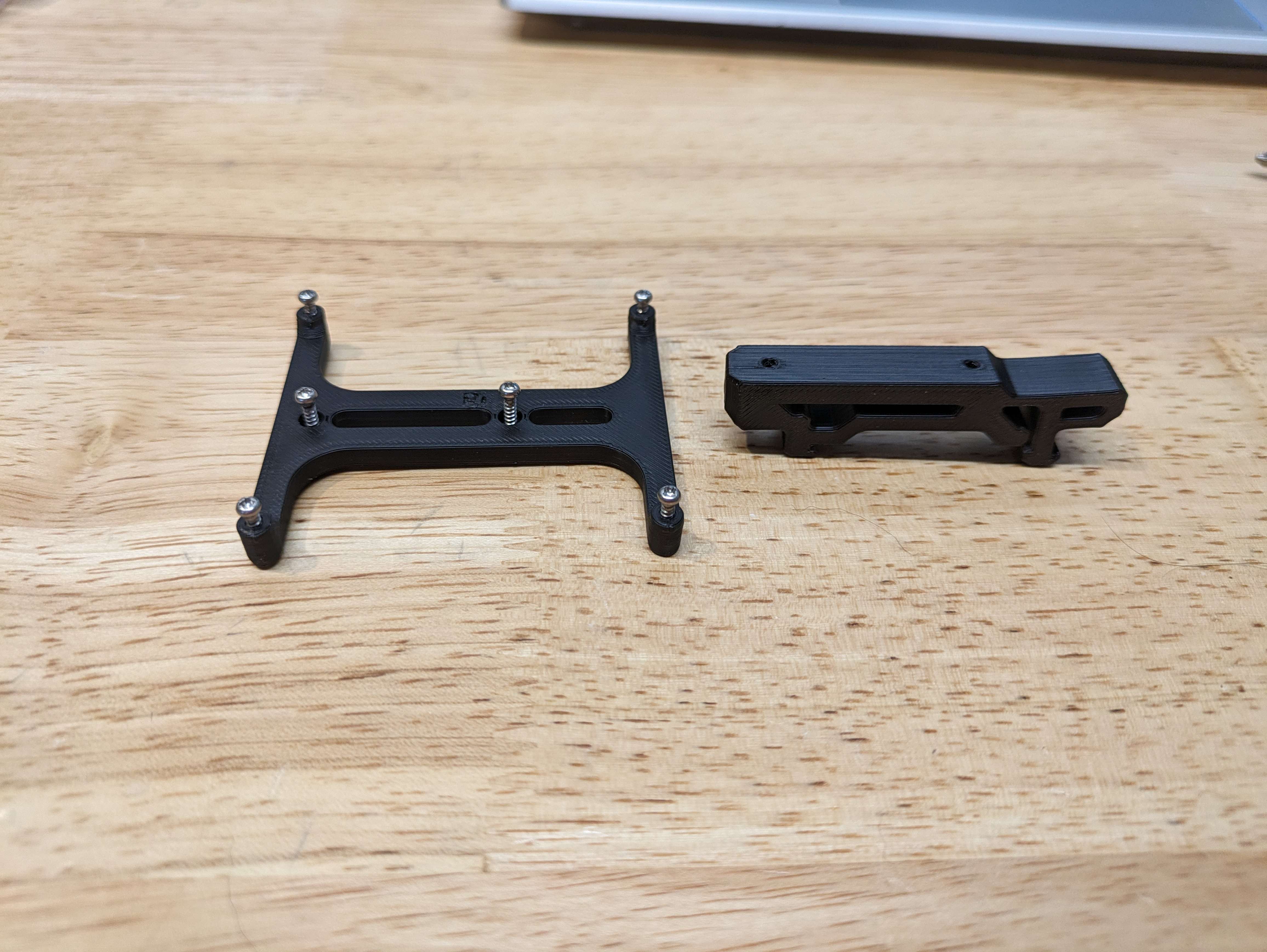
¶ Raspberry Pi Mount
- Using the m2x10 self taping screws you will face the clasp end to the right on the bottom and then line up the two holes to screw in the carrier to the din rail mount portion.
DO NOT OVER TIGHTEN as doing so will strip out the self tapped threads from the screws and will make the mount loose.
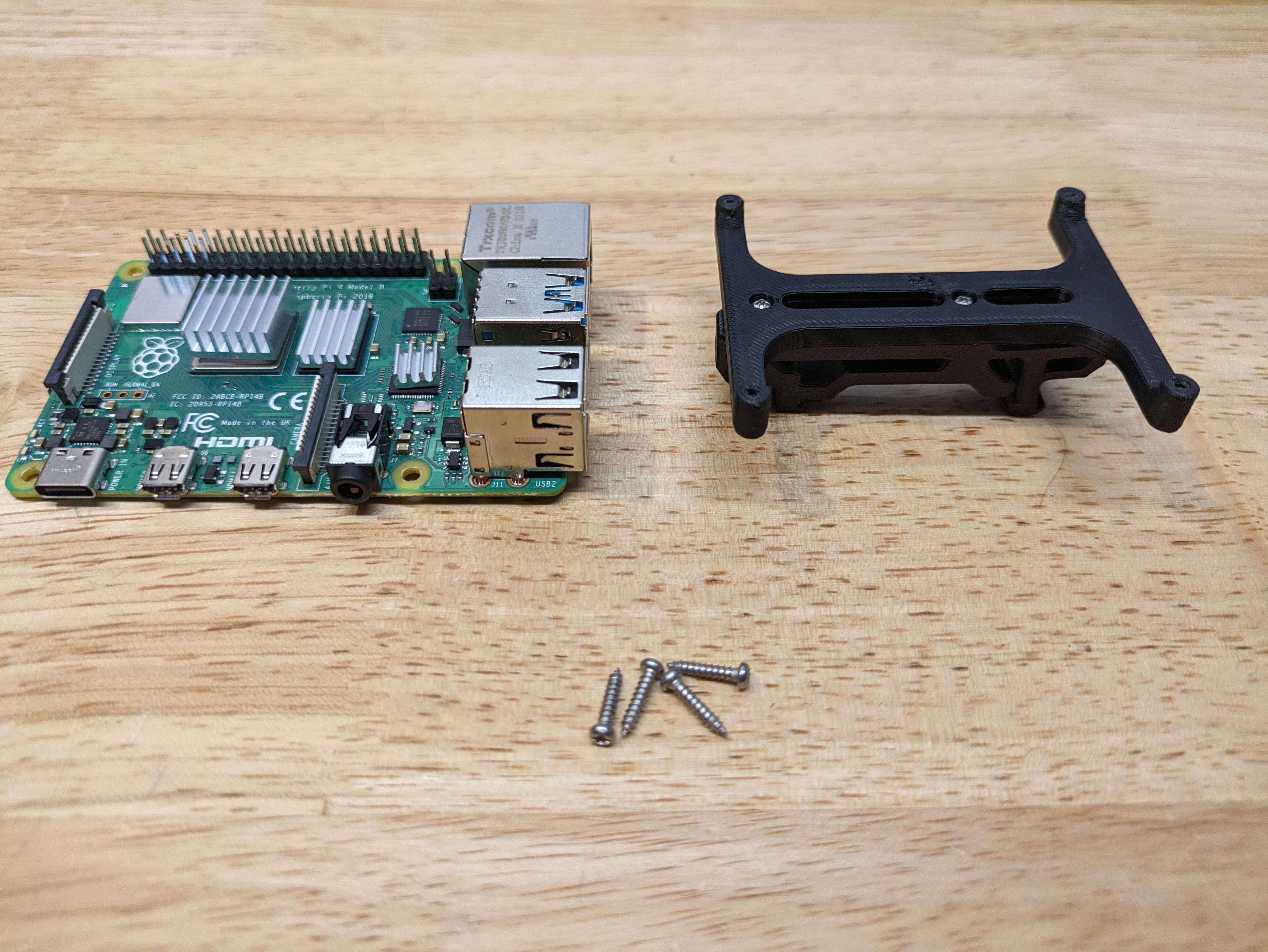
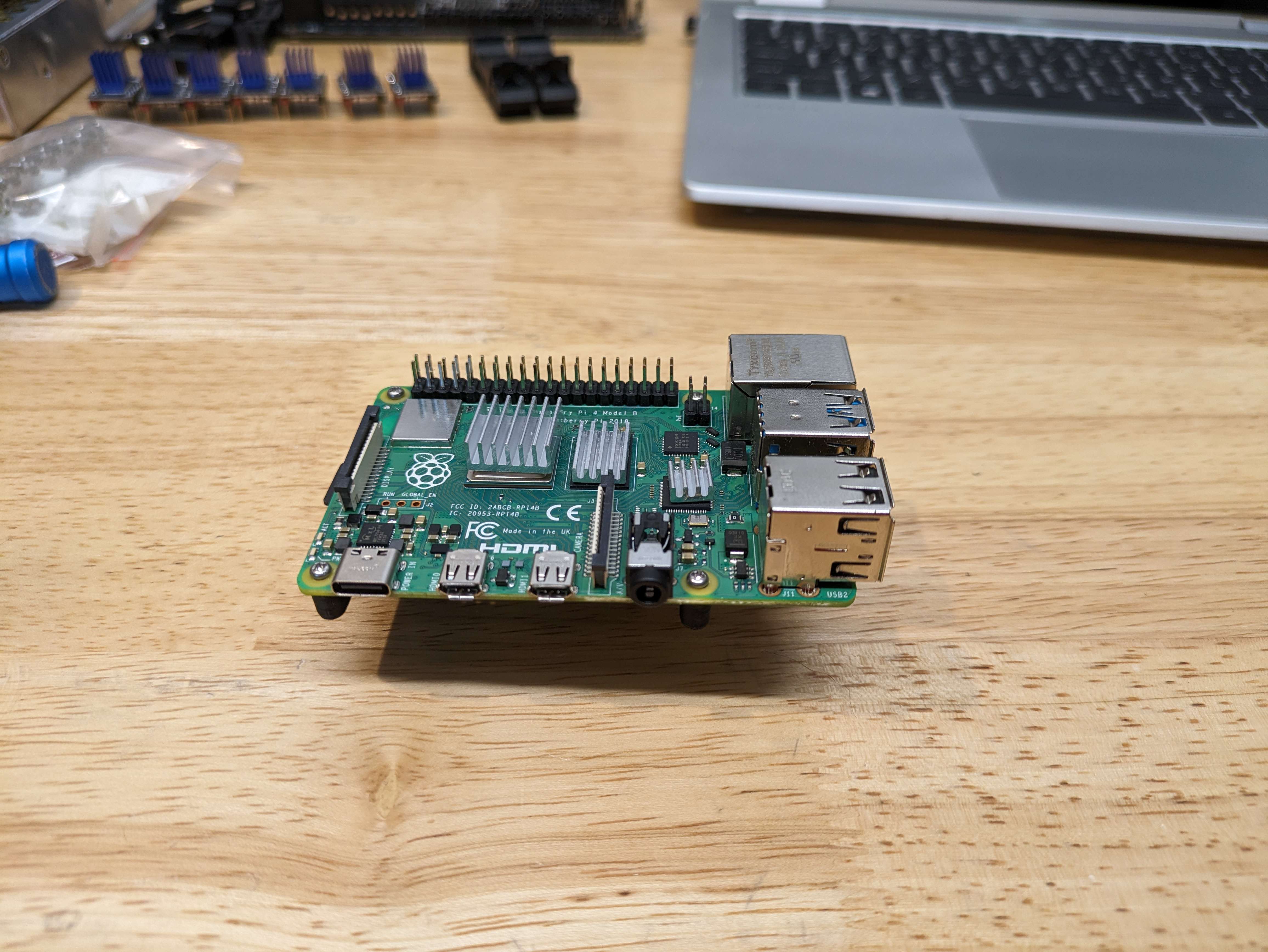
- Utilizing 4 more M2x10 Self tapping screws we will line up your Pi of choice to the carrier plate and will start all 4 screws in a star pattern so that it is equally tightened to the mount, Bottom left, Top Right, Bottom Right, Top Left.
- Once this is mounted and tight to not move on the mount you can place this in a safe area to be added to the Din Rail in later steps.
¶ 5V Power Supply Mount
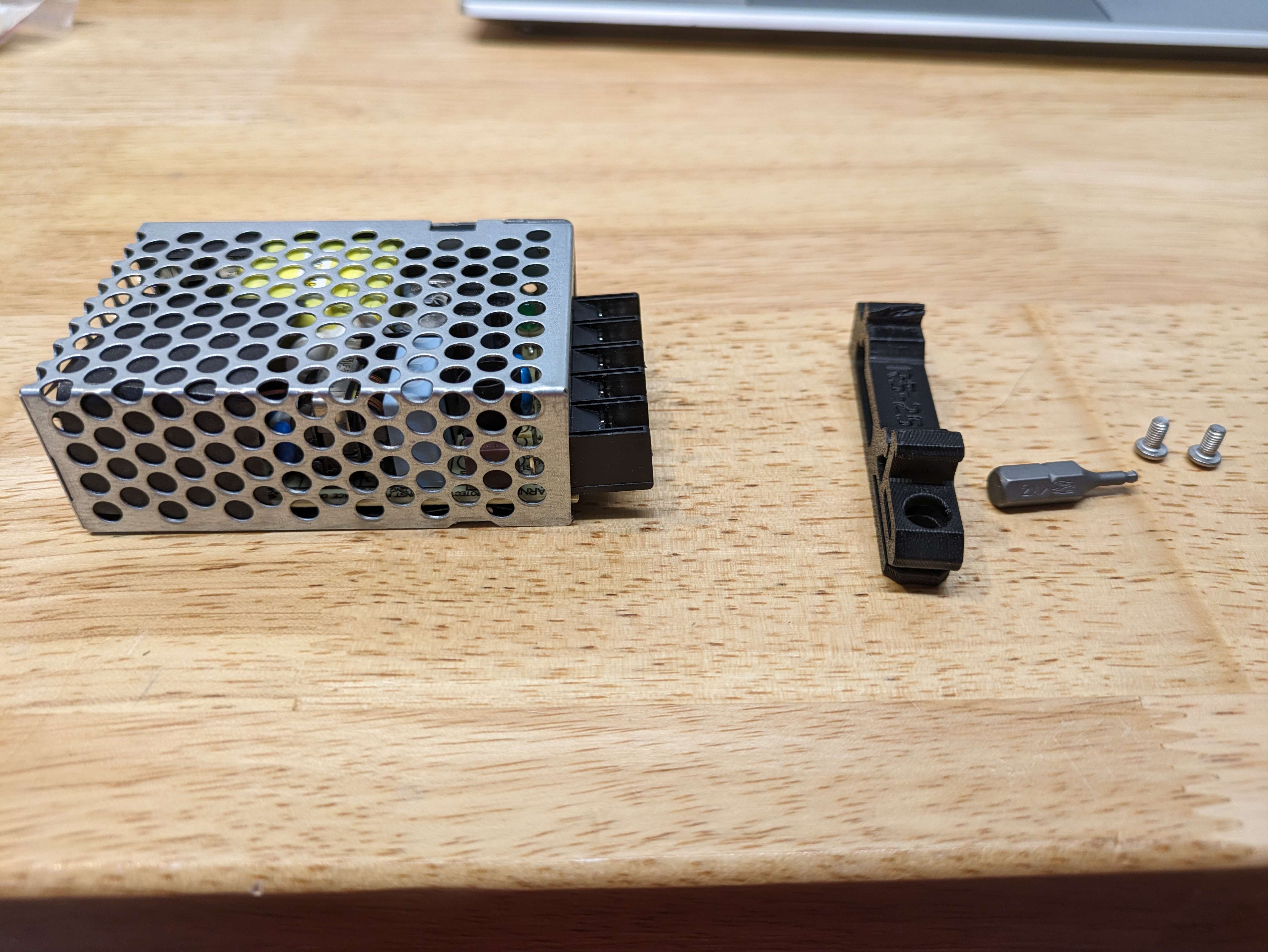
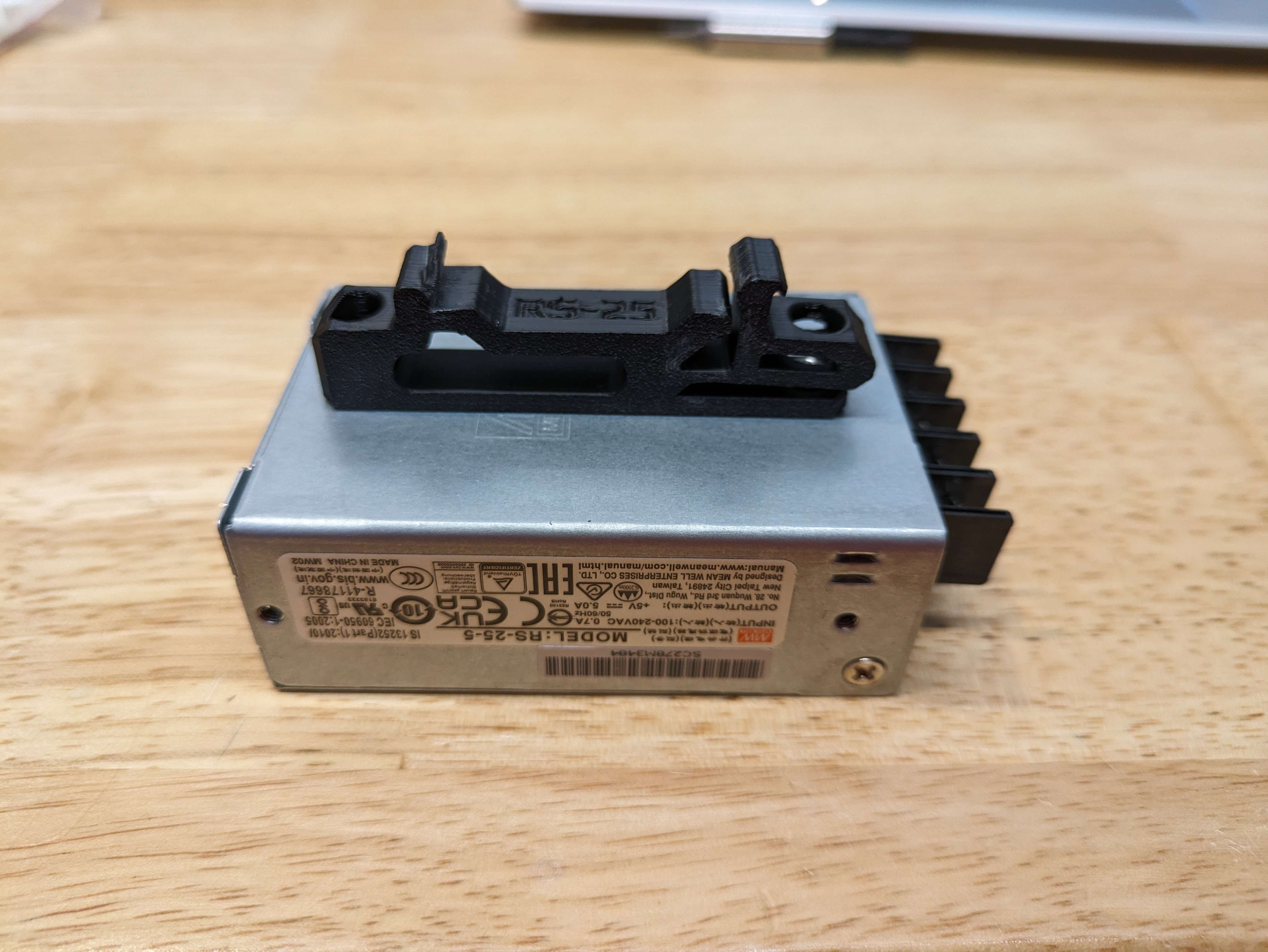
- Use the size 2 hex head to mount the 2 - M3x6mm Button Head Screws to the Power Supply.
¶ 24V Power Supply Mount
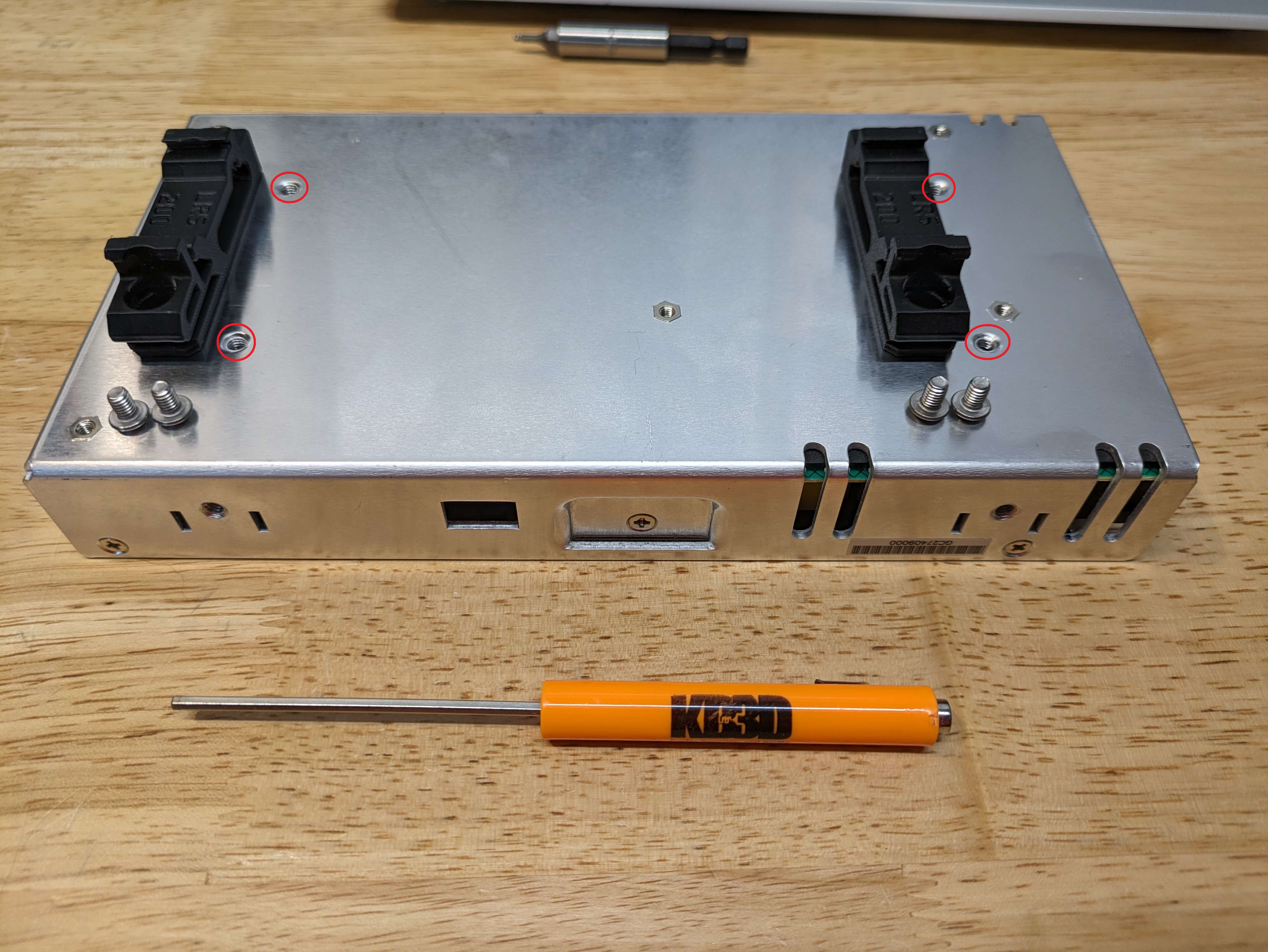
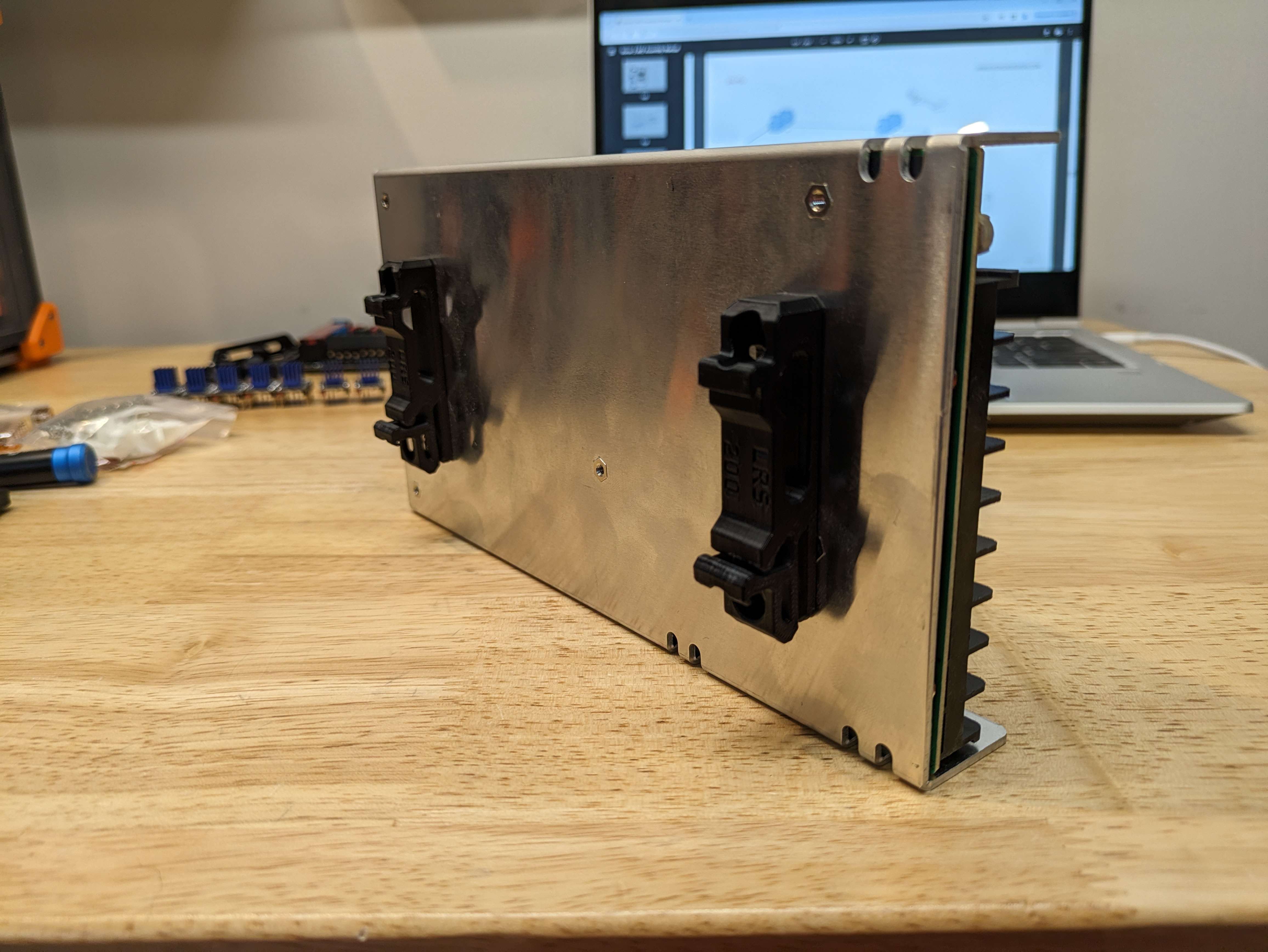
- You will need to use the M2.5 Hex Head tool to install the M4x6 Screws into the holes that are noted in the image below, Take note to place the latches towards you and to have the connectors for the wires on the right hand side. This will be in line with how the Voron Manual is setting up this power supply.
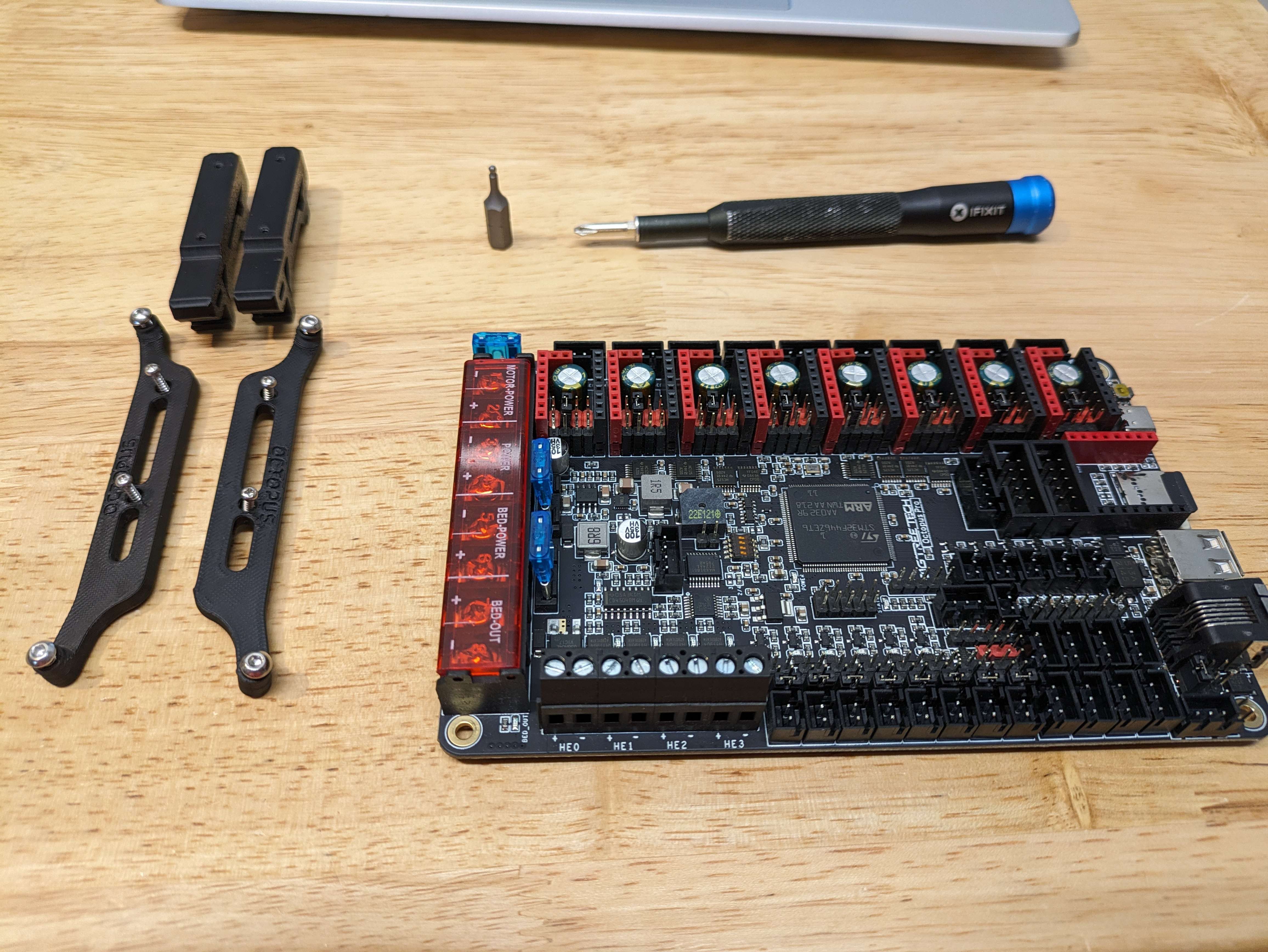
¶ Controller Board Mount
We are currently on Page 154 of the Voron Manual for 2.4’s we will be working on getting the controller board mounts placed.
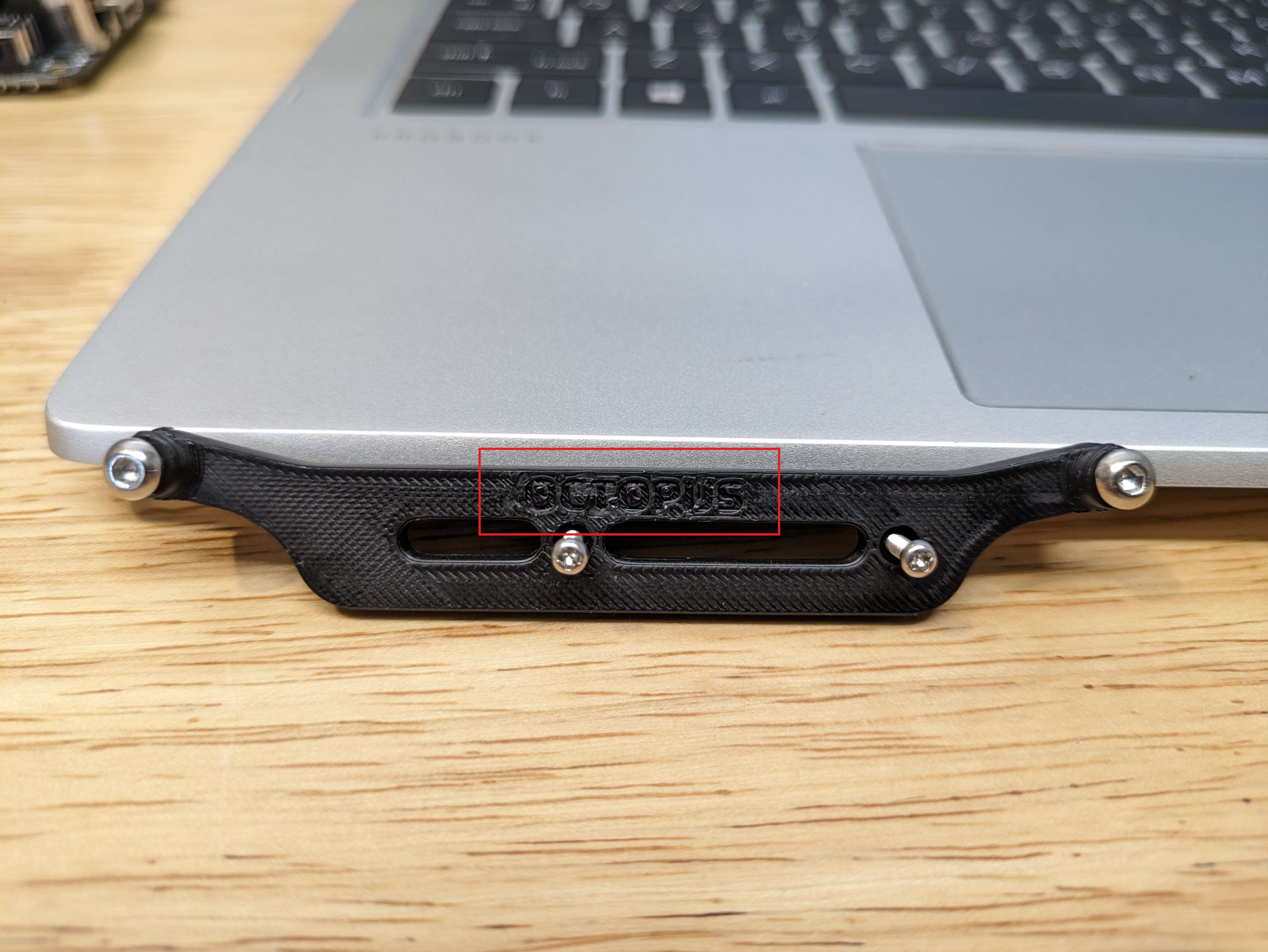
Quick Note - There are various controller boards that are being used for Voron’s we are using an Octopus Pro for this installation. Note that the Controller board Mounts are labeled on the pieces so you can get the correct ones
First we will use the M2x10 self tapping screws to mount the controller board mounts to the din rail mounts. * Do Not Over Tighten the screws they will strip the plastic*
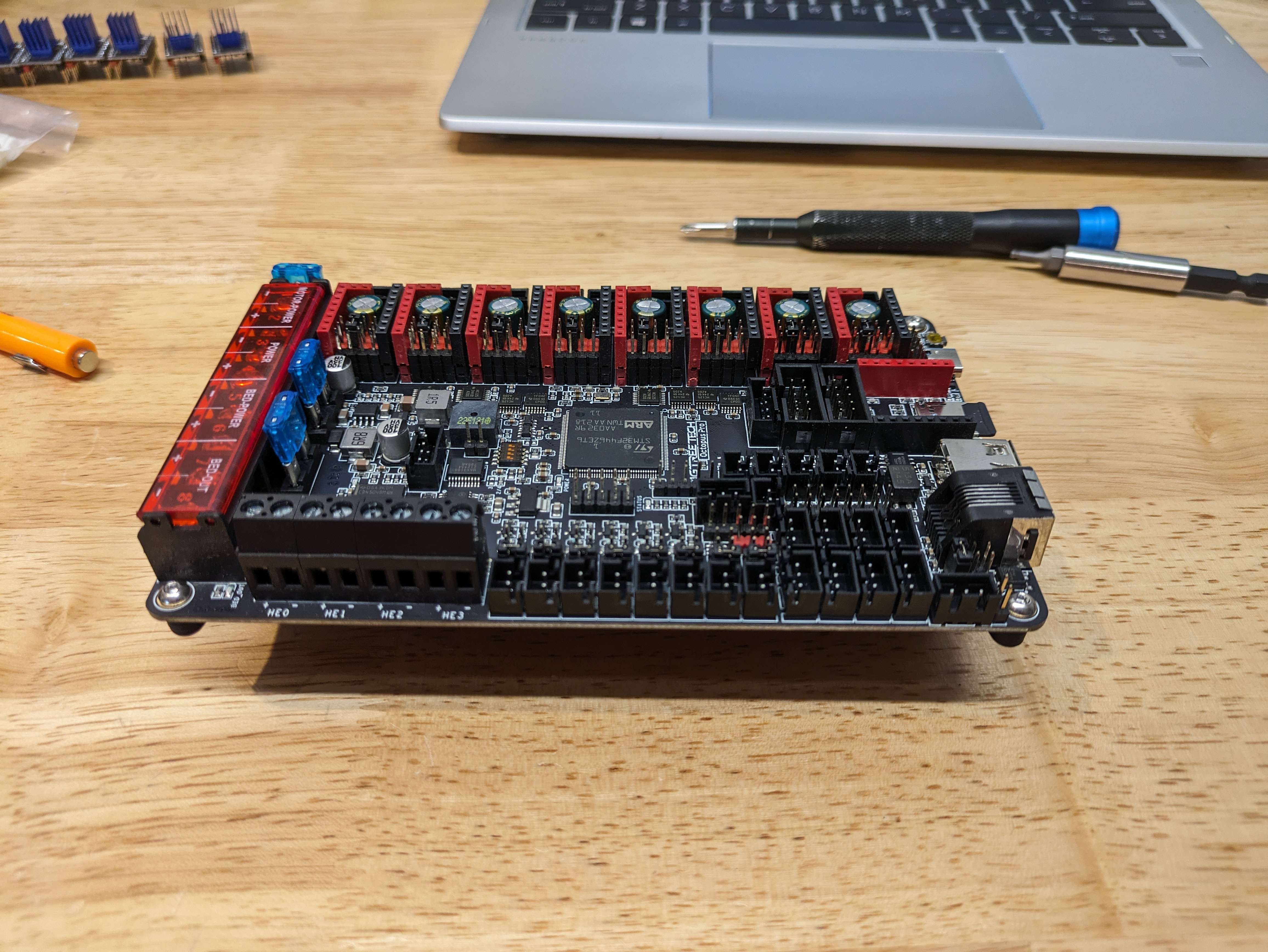
- After the controller board mounts are attached to the Din Rail mounts you will use 4 - M3x6 Button Head Cap Screws to mount the controller board of choice to the controller mount.
¶ Power Inlet
- First you will want to make sure that you have the heated inserts set into the part like we have done earlier in the Voron manual they will be circled in red on the image below.
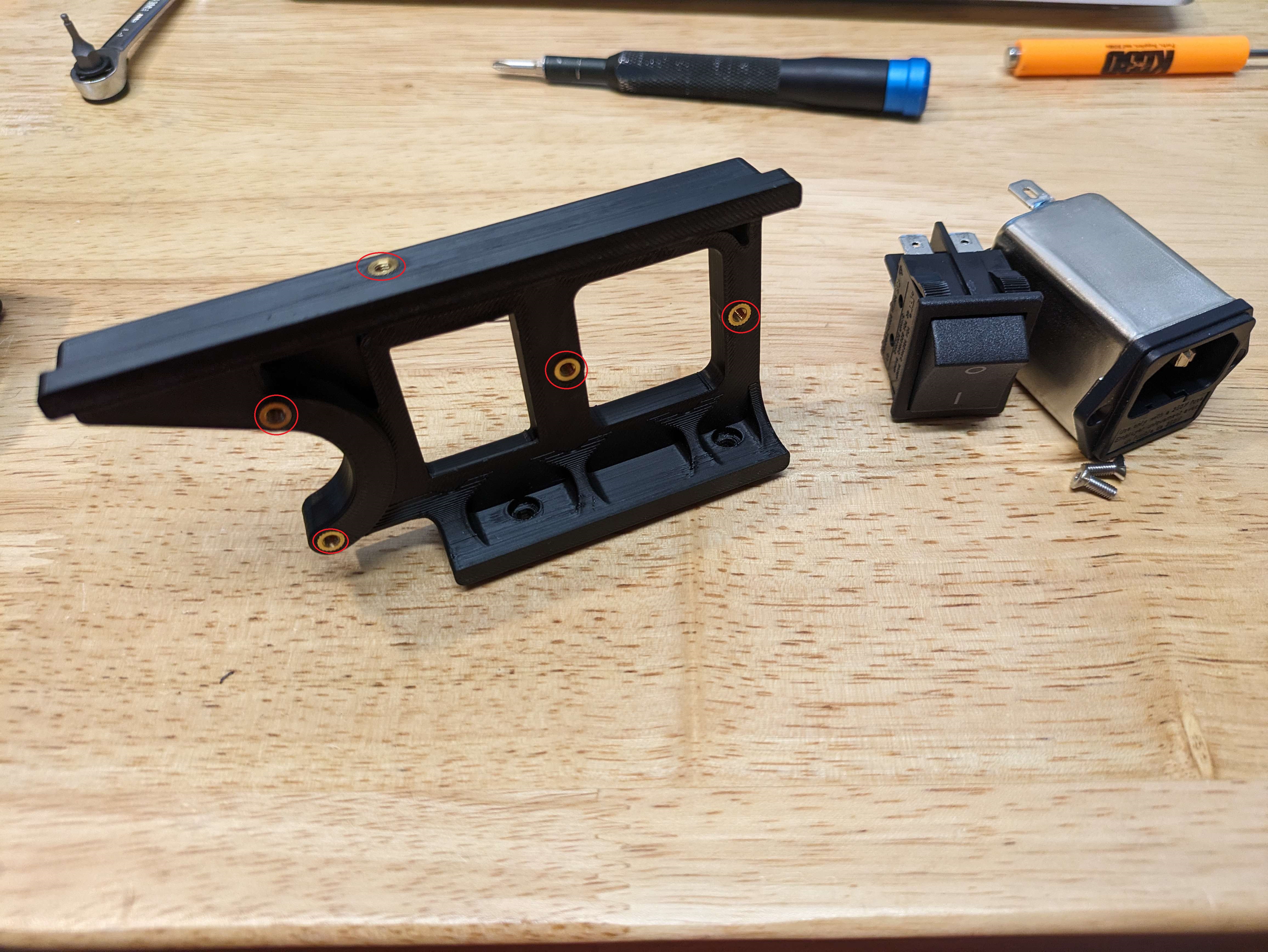
- You will use the 2 - M3 x 10 Flat Head Cap Screw to screw in the filtered inlet to the printed part. You will then place the switch into the square hole and making sure to push it evenly into the opening to ensure it does not go in at an angle.
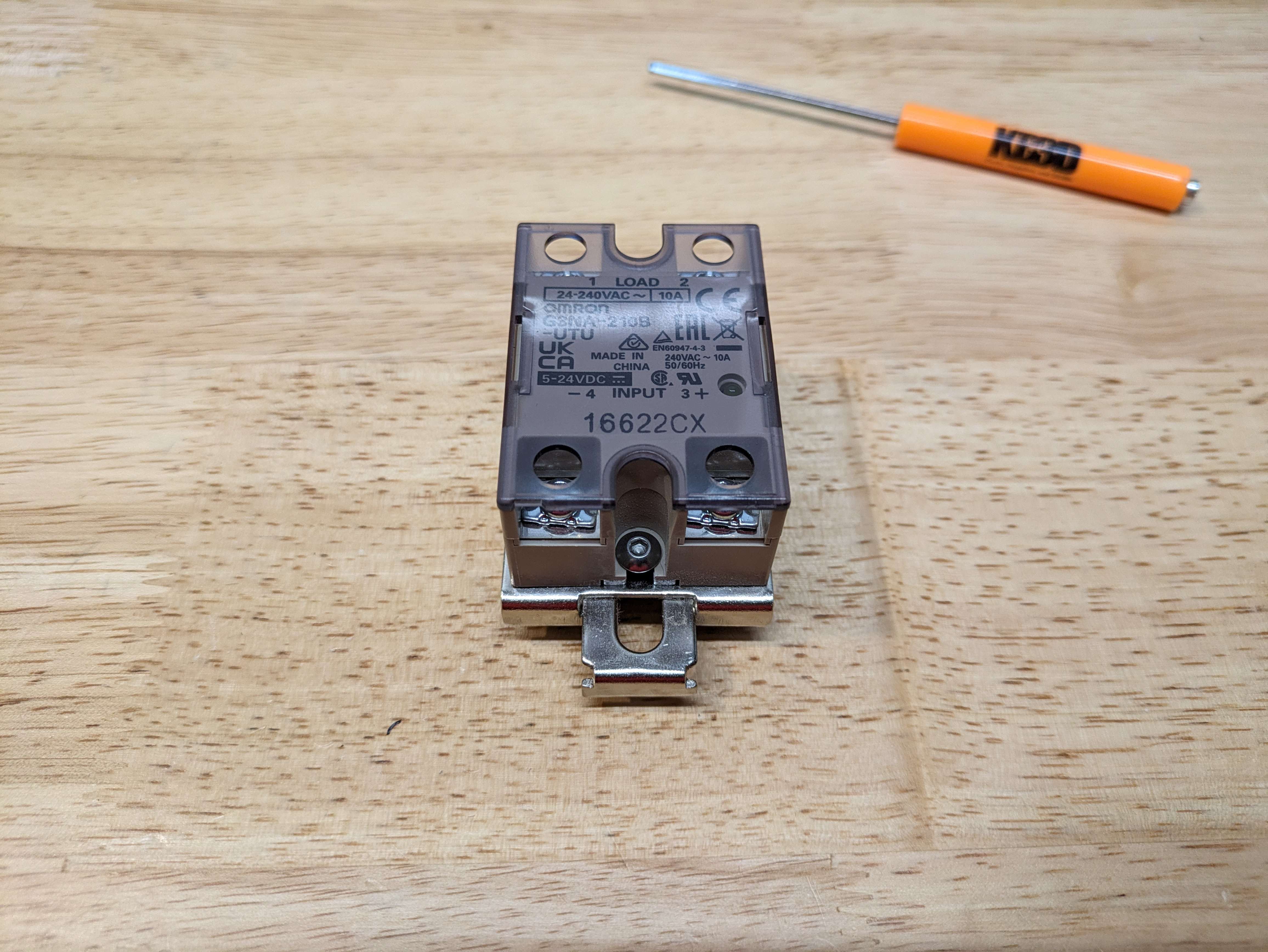
¶ Solid State Relay ( SSR )
- On page 157 of the Voron manual, you should have 2 - M4x6 screws and the din rail plate and the SSR, Just place the SSR onto the Din rail mount and screw into the two provided holes that line up, don't over tighten as the din rail mount will strip if you go too tight.

¶ Wago Mounting & Power Inlet
-
We will be utilizing the Wago's that are provided in the Linneo Under The Deck Wiring Kit.
-
We will be working with your printer upsidedown from here forward for mounting and wiring.
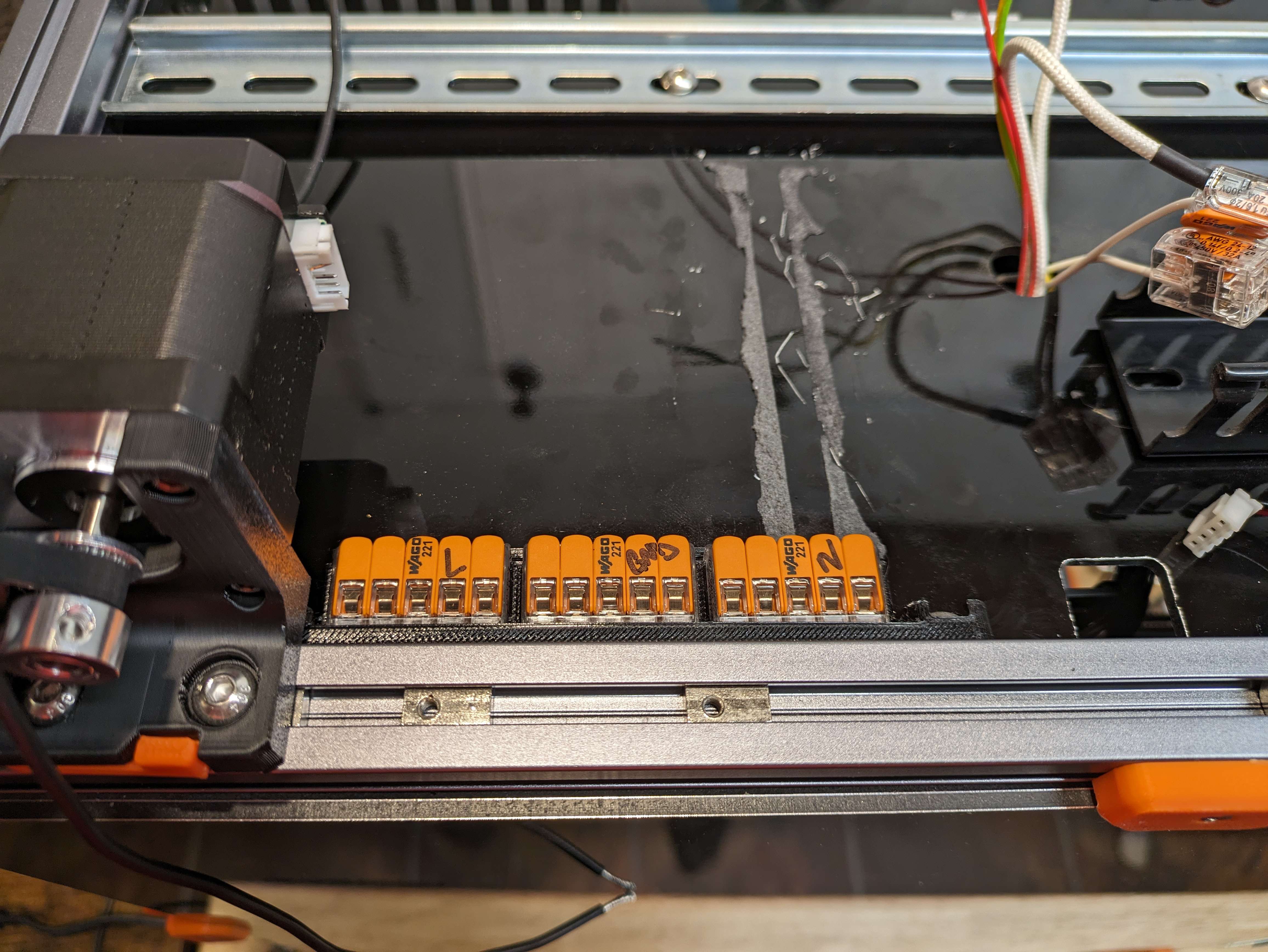
- In your printed parts kit if you got this from the Print It Forward Program, there should be a extrusion mount for the 3 slot 5 Port Wago connectors.
- You will be placing them in the rail like it shows on Page 165 in the Voron Manual.
- Take the 2 - M5x10 BHCS and place them through the mount for the wago's and mount it like in the picture below.
I suggest Marking them From Left to Right L GND and N so that we can keep track of the wires.
-
In the previous picture you can see the two M3 TNuts that were placed in the rail following the Voron Manual on Page 166.
-
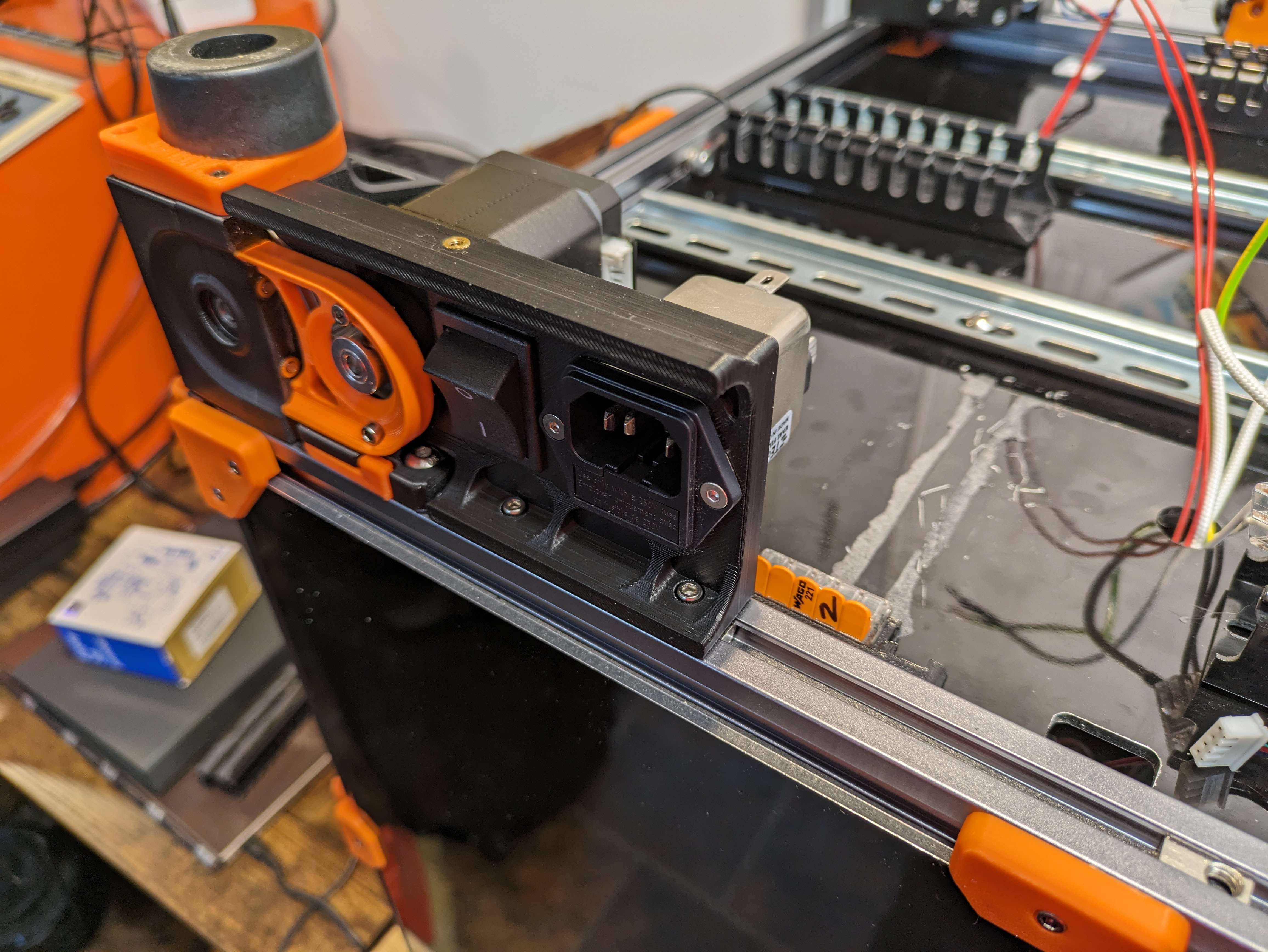
While in this orientation and in the same corner we will be mounting the Power Inlet next to the motor.
-
You will place the M3x8mm screws through the power inlet shroud into the tnuts and tighten them down.
¶ Din Rail Mounting of Hardware
- In this section we will be mounting all of the elctronics hardware to the din rails, we will be following the Manual at page 168. The way to mount the hardware with these mounts is to take the static catch side and hook it to the rail and then rock the connector onto the other side of the din rail.
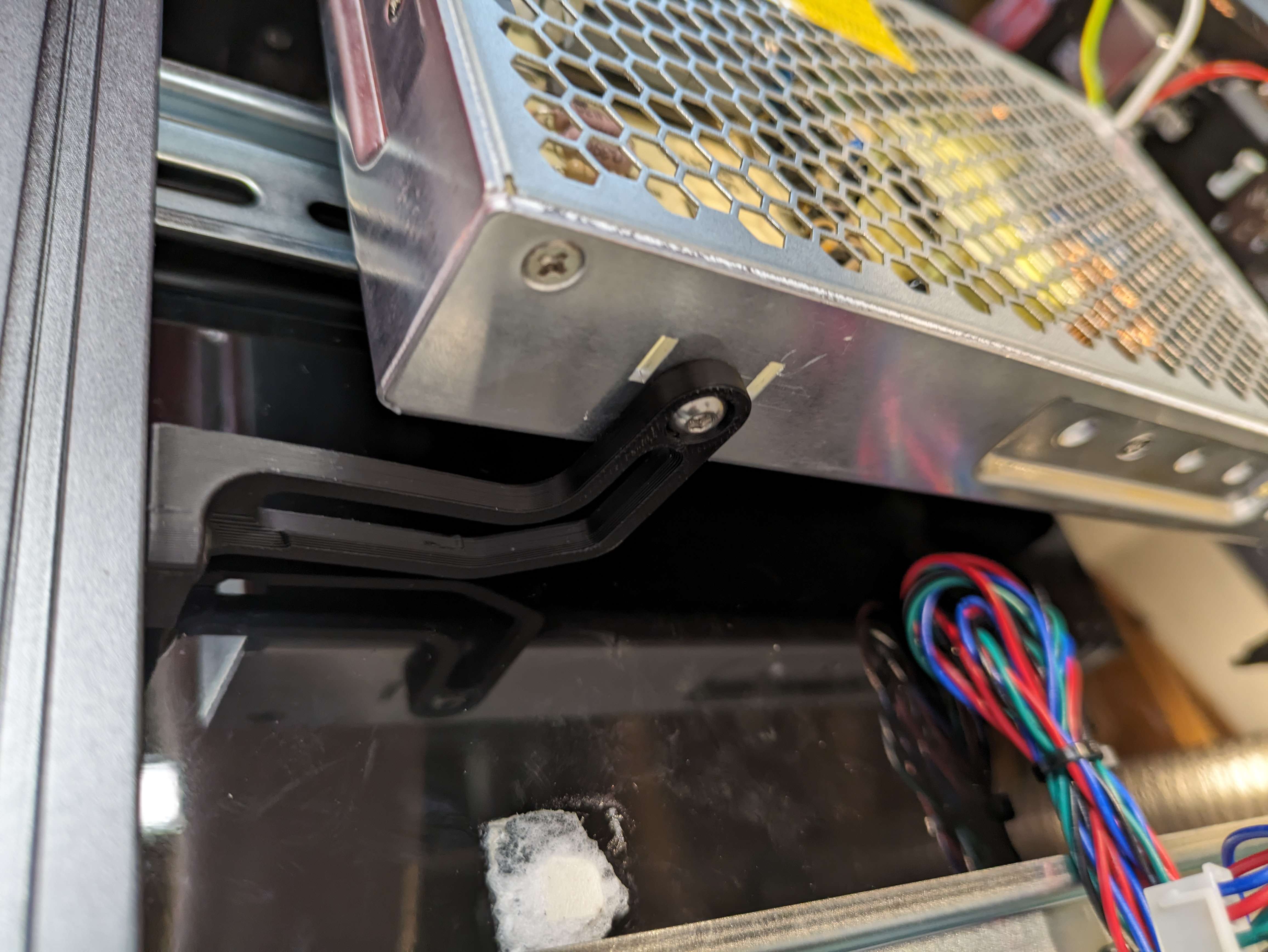
¶ 24v PSU Mounting
First we will be mounting the 24v PSU, with the connectors facing left from you, you should be and to place the rear part of the mount onto the din rail and rock the mount down toward you to get the clips to clasp the rail.
There is a mount that is also on the back corner that is attached to the extrusion, this will require a m5 T Nut and then 1 M5x10 BHCS and 1 M4x6 BHCS to mount the PSU into the electronics deck. The M4 goes into the PSU.
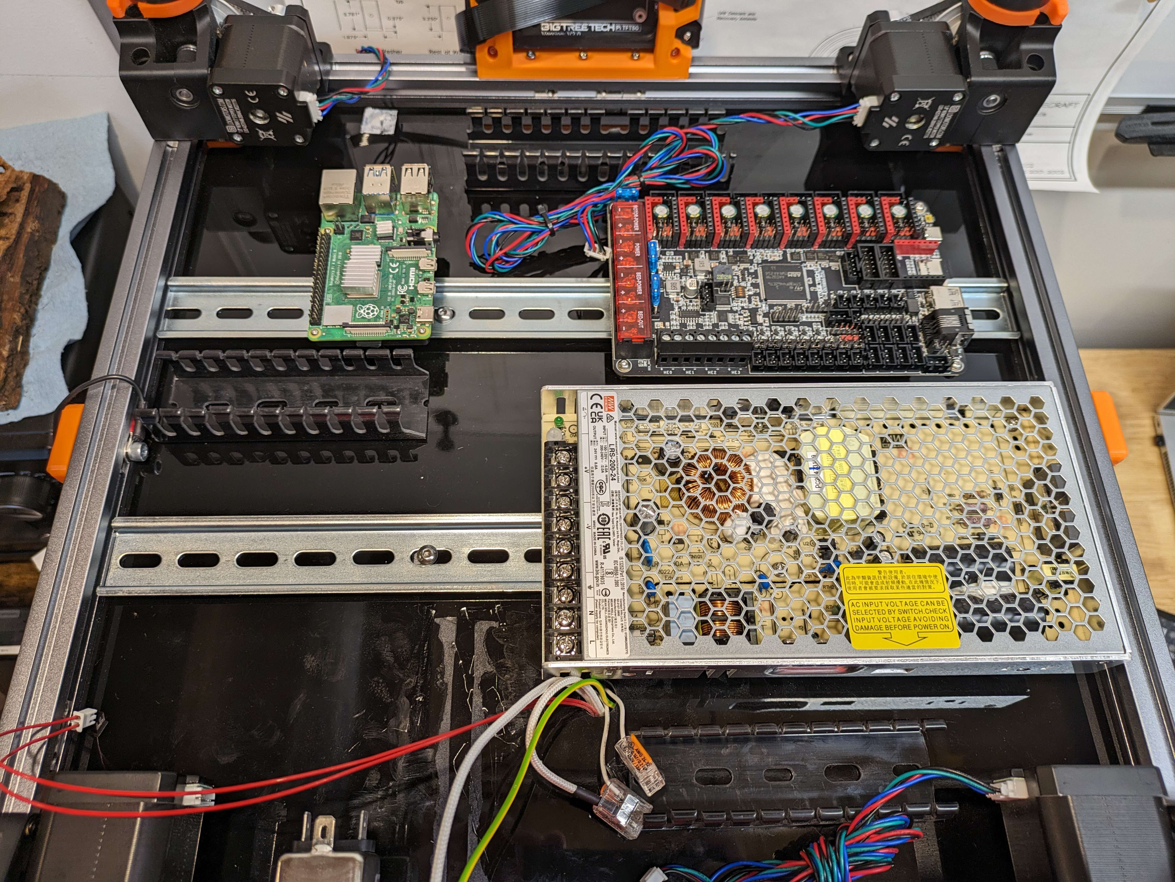
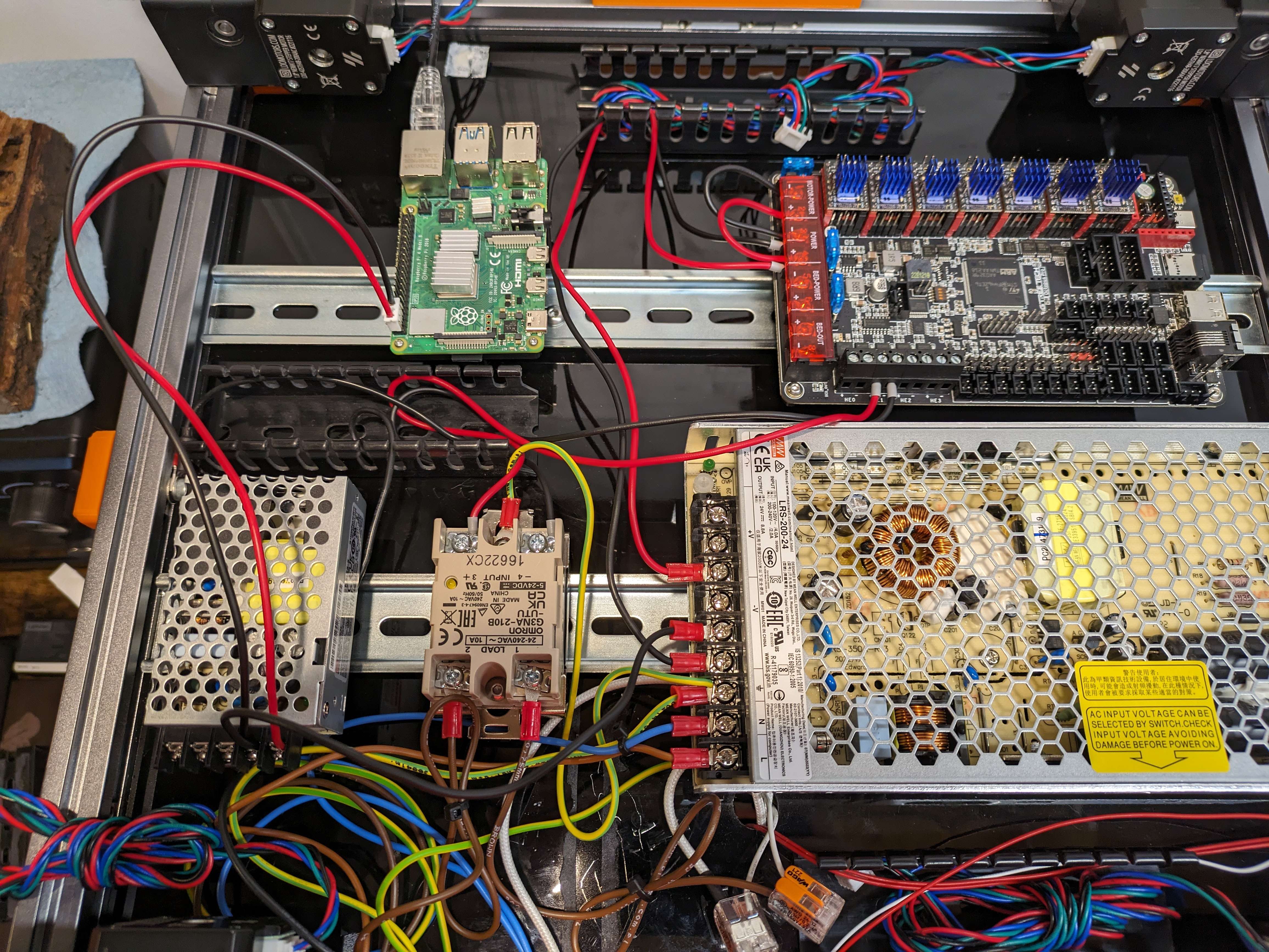
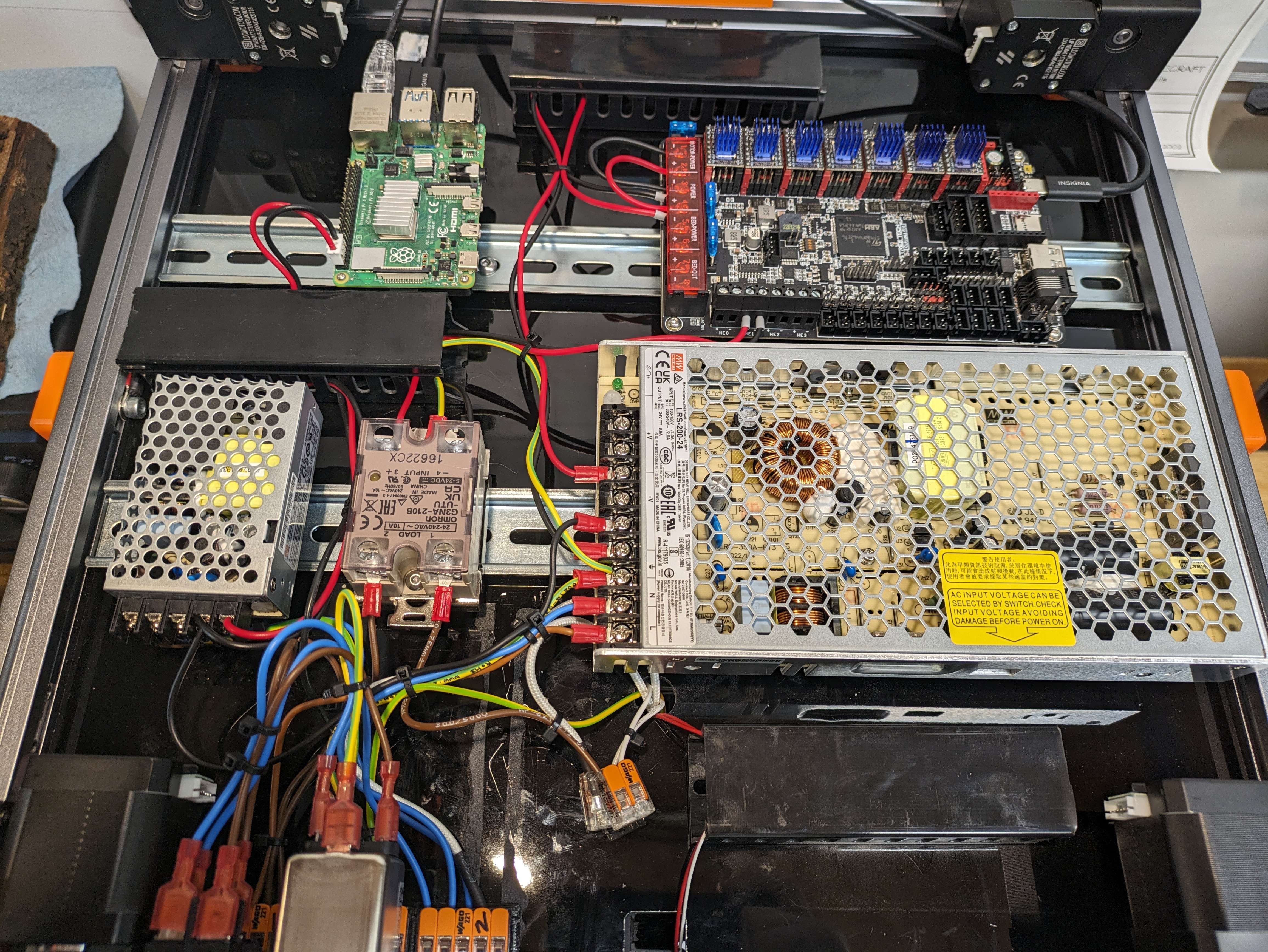
¶ Pi & Controller
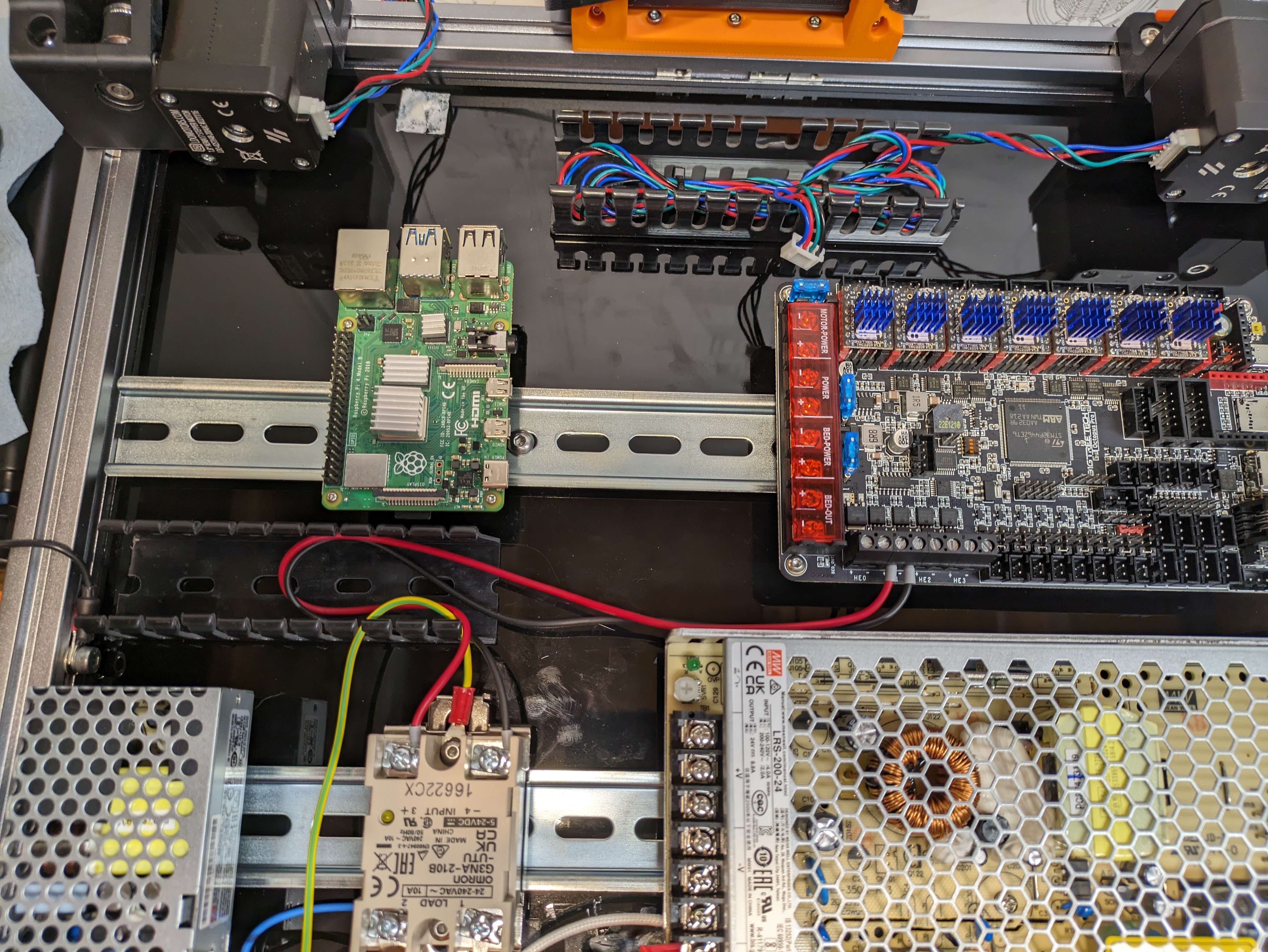
From Page 170 we will install the Pi & Controller of choice into the Electronic Deck, The controller board goes above the 24v PSU, the Pi takes home on the left hand side of the controller board on the same Din Rail. Make sure to have the screw terminals on the left hand side of the controller board.
It should look like the image below when complete
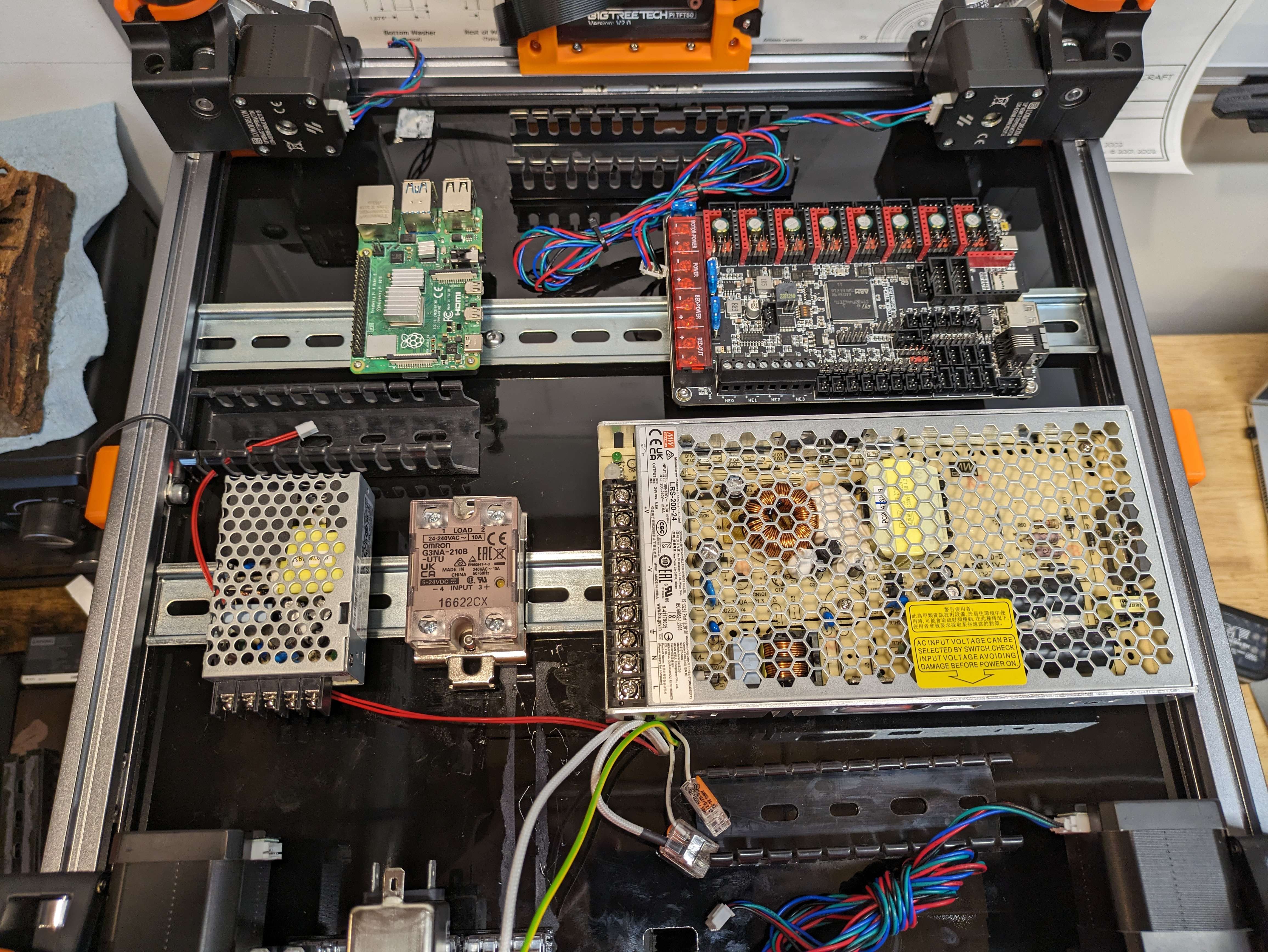
¶ Solid State Relay ( SSR ) & 5V PSU
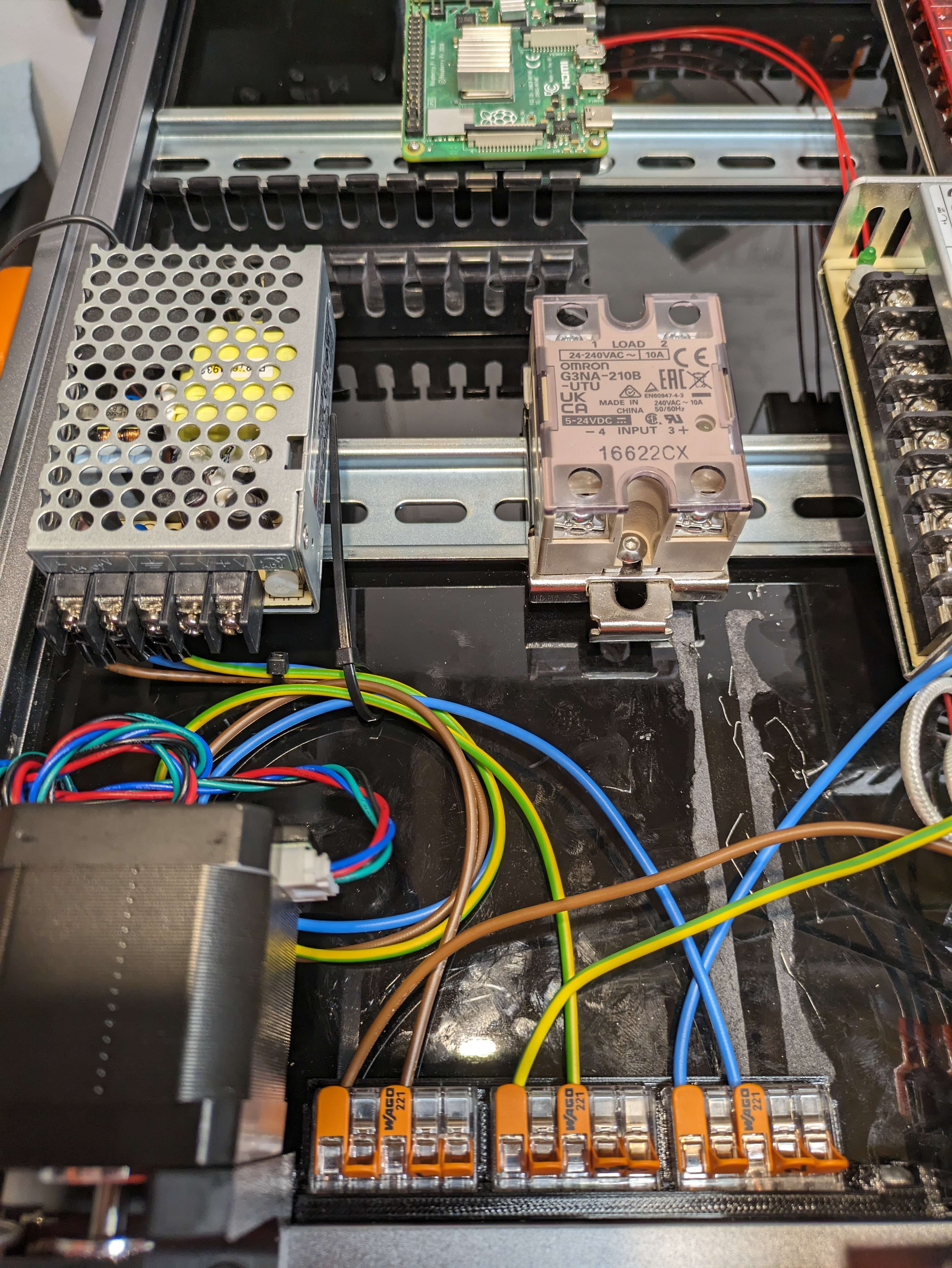
From page 171 in the Voron Manual we will mount the SSR to the Din Rail right next too the 24v PSU.
This has a spring loaded mount, so this will be able to be squeezed and then place it on the lower rail we want the -4 3+ inputs facing the bottom.
From page 172 you will place the 5v PSU right next to the SSR on the lower Din Rail, this will keep all the lines short for the things we need.
We will be skipping the Controller Board Configuration in this Guide. Jump to Page 180
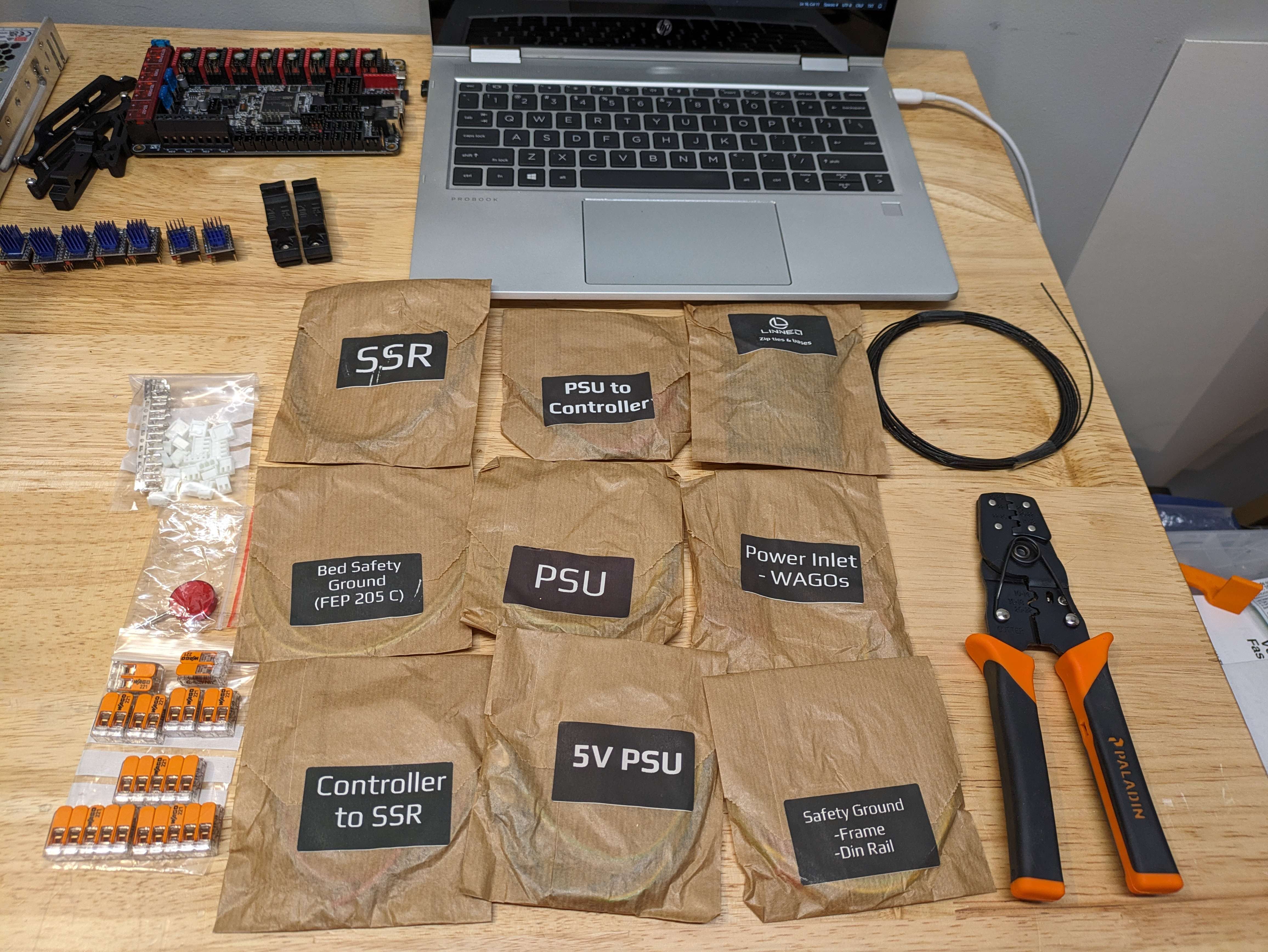
¶ Wiring
Now we will be using the under the deck wiring kit from Linneo.
You should have all of the items currently placed in this photo within your kit.
The crimpers are sold seperately*
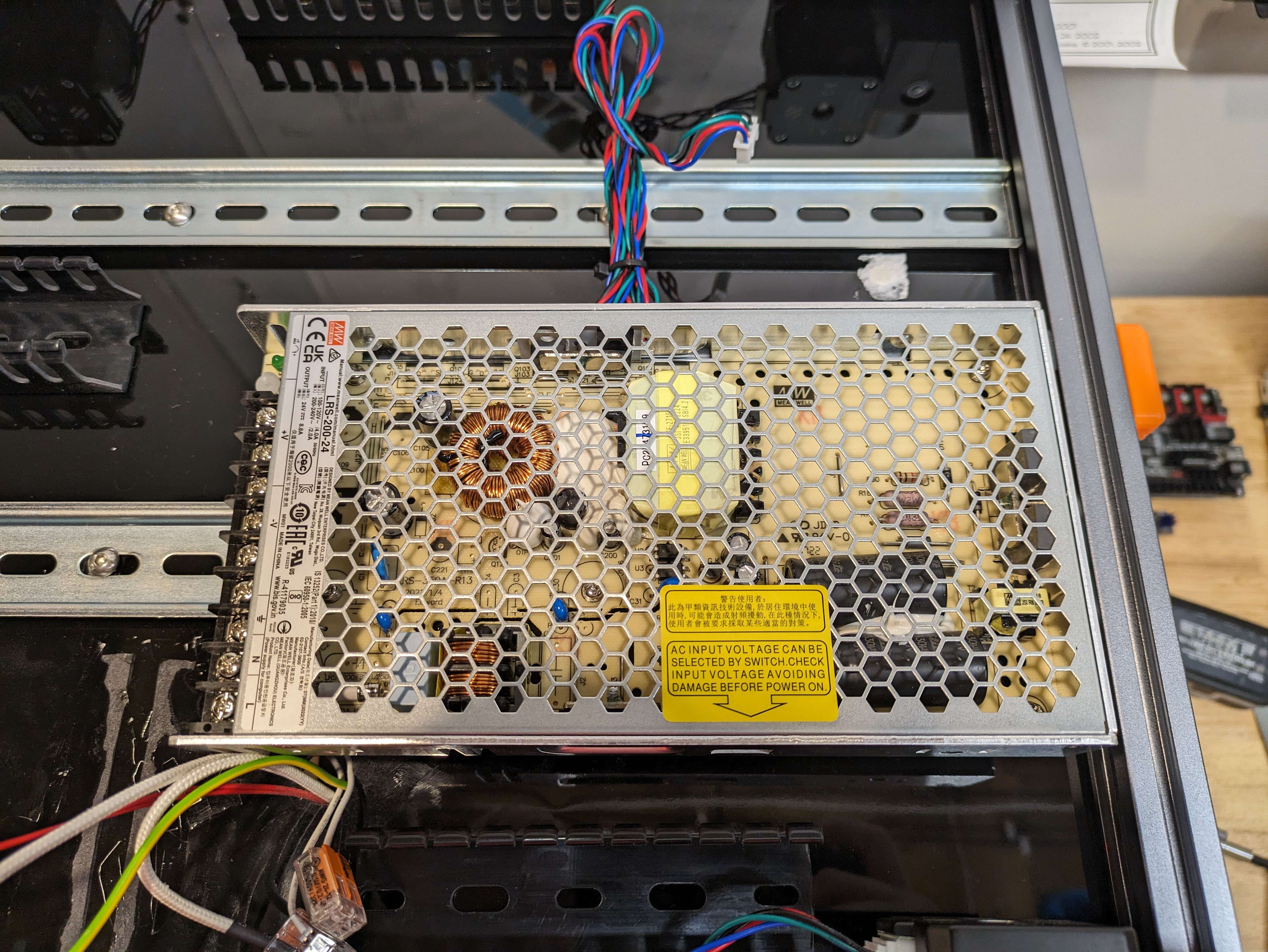
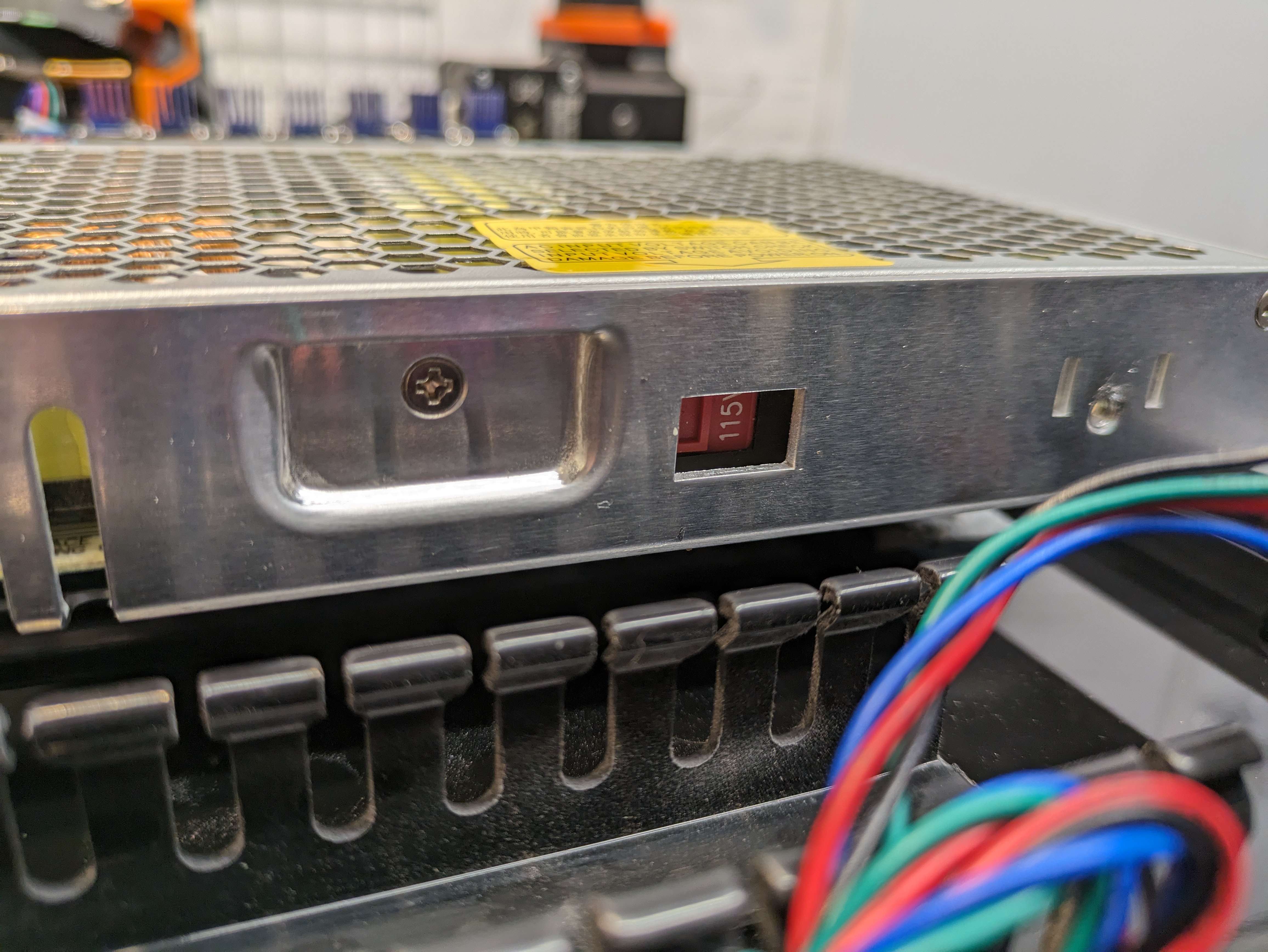
¶ PSU Voltage Check
- We will be checking the input voltage for the 24v PSU, on the side there will be this little slider that will flip between 220 and 115. If you are using 220v then make sure it is on 220, if you are using 115v then make sure that it is set to 115.
¶ Power Inlet Wiring
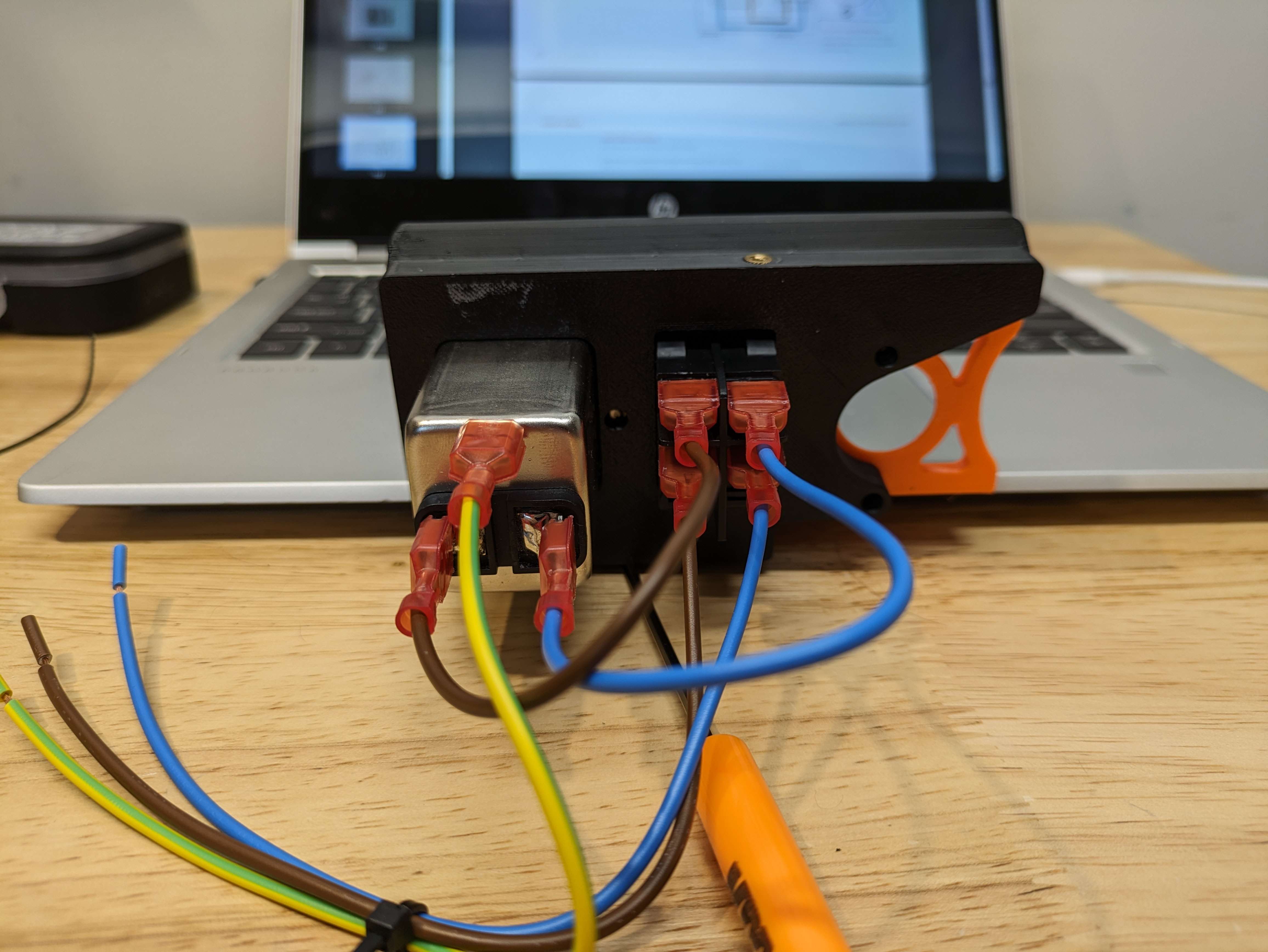
In this section I have removed the power inlet so that it is easier to see.
We are following the Page 182 Wiring for the Power Inlet.
Note: This view from the manual is a rear view as if you are looking at it directly.
Verify the orientation of the switch before moving on we will want to have the extra space facing up.
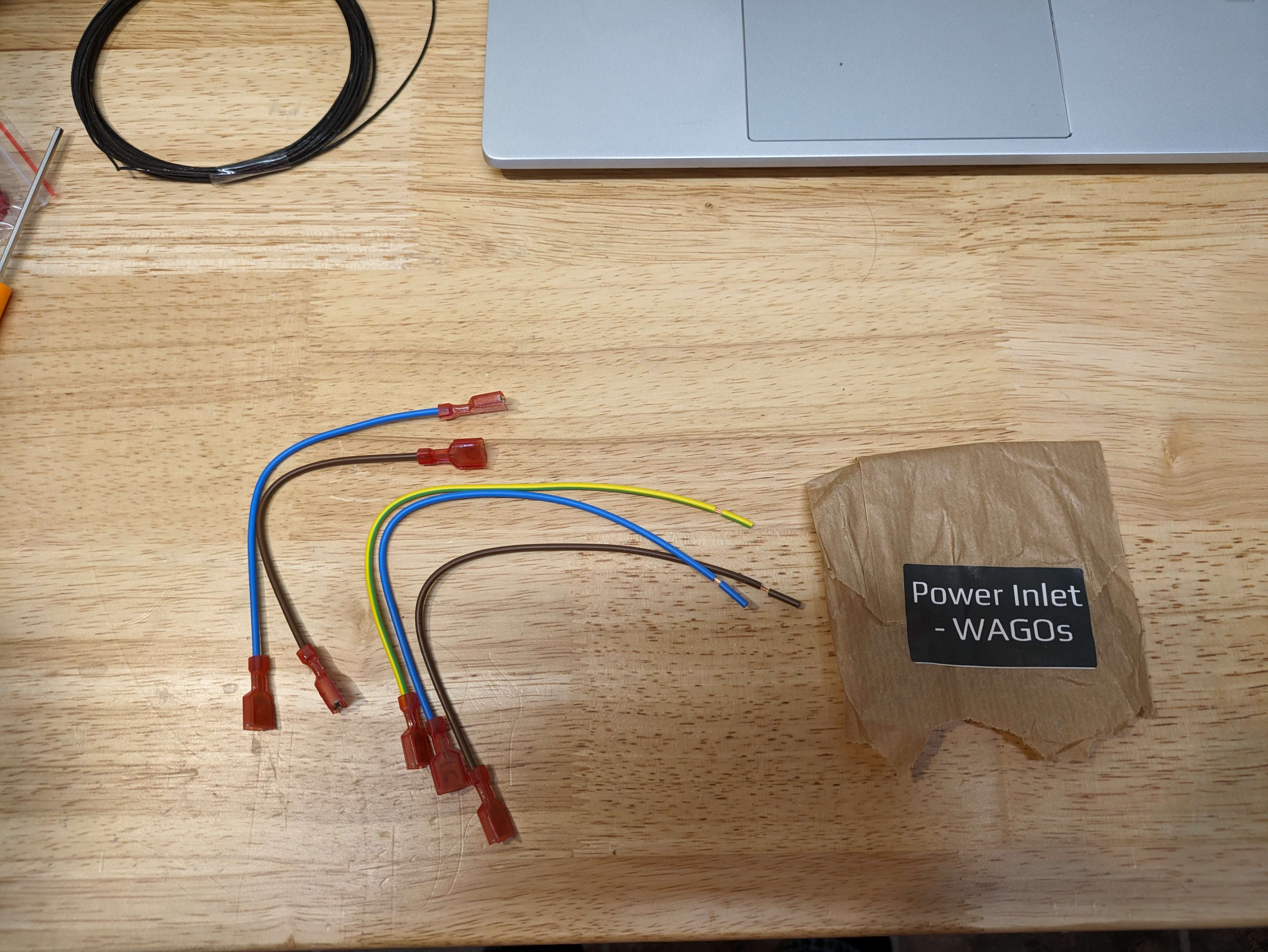
- Find the Power Inlet Wagos package, When you open it, there should be the following inside:
- 1 Blue Wire with a femal spade connector at one end and a pre-cut end on the other.
- 1 Brown Wire with a femal spade connector at one end and a pre-cut end on the other.
- 1 Yellow/Green Wire with a femal spade connector at one end and a pre-cut end on the other.
- 1 Blue Wire with a female spade connector at both ends.
- 1 Brown wire with a femal spade connector at both ends.
- We will start with the Ground, Following the Voron Manual you will place the Yellow/Green wire, female spade connector on the ground pin of the Power Inlet.
- We will then take the blue wire that has two female ends and place it on the bottom left side of the Power inlet, then we jump that over to the far right lower spade connector.
- Then the Brown wire with the two female connectors and place it on the power inlet on the right spade connector. We will take this over to the lower left spade connector of the switch.
- With the last two wires we will follow the colors on the switch and place the blue wire with the 1 female connector will get connected to the top right spade connector on the switch.
- The last brown wire with the one female connector will get plugged into the top left spade connector of the switch.
¶ Mains Wiring.
This section will be over viewing the Mains Wiring from Page 183 in the Voron Manual.
Pages 183 and 184 are more of references to what the final product will be when complete.
¶ SSR to Controller
On page 185 you will start wiring with the SSR to the Controller.
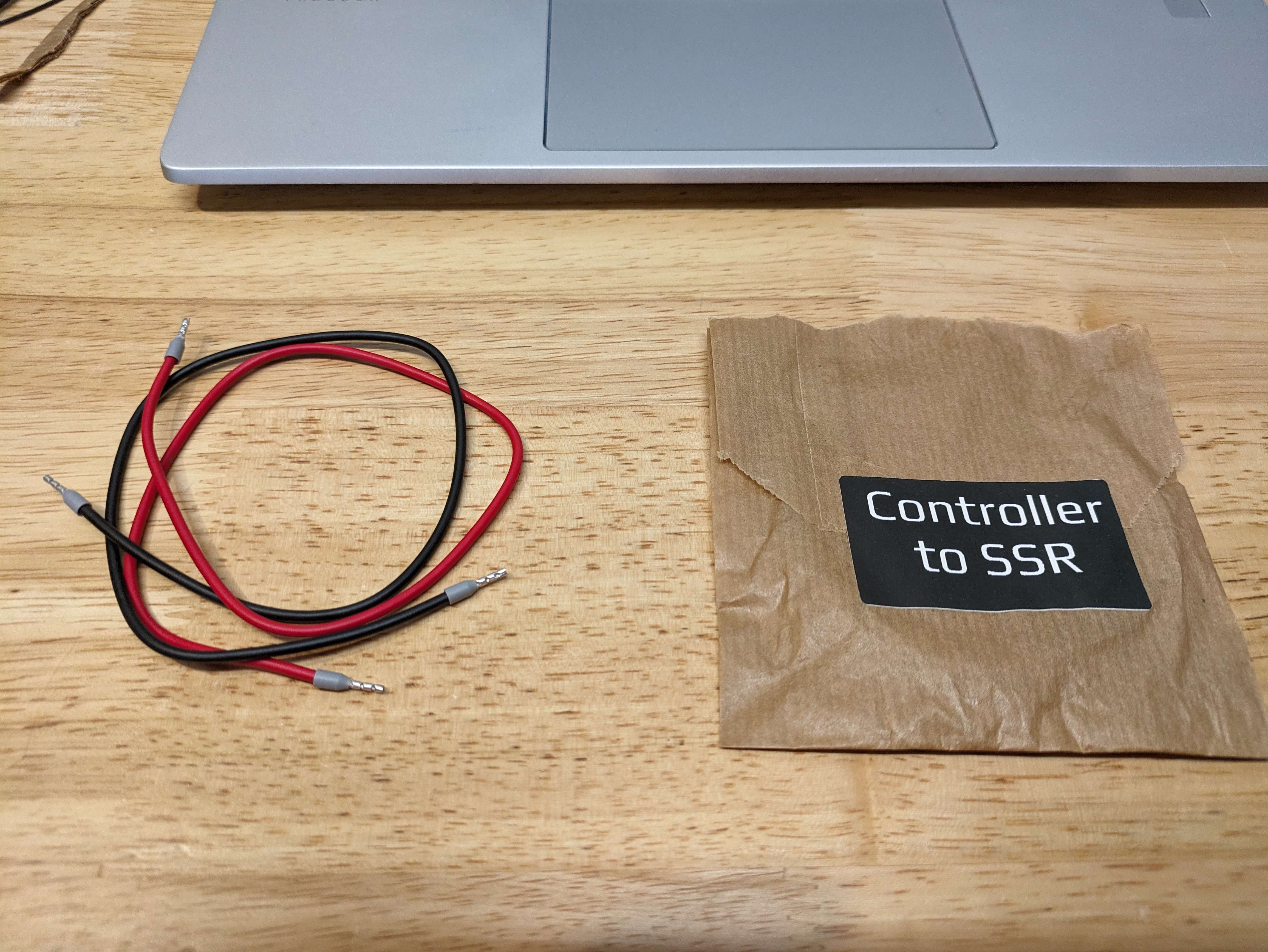
These wires have double ended Ferrule Crimps on them, these are common for making connections in Controller boards.
In the diagram on 185, it shows the 4- and 3 + on the opposite sides from the image you will see below. We will place the red end into the #3 spot and then the black wire into the #4 spot.
Because i do not like leaving things have complete, the Other end of the Red wire goes to HE1+ and the Black wire will go to HE1-.
We will come back to the Bed wiring in a few steps.
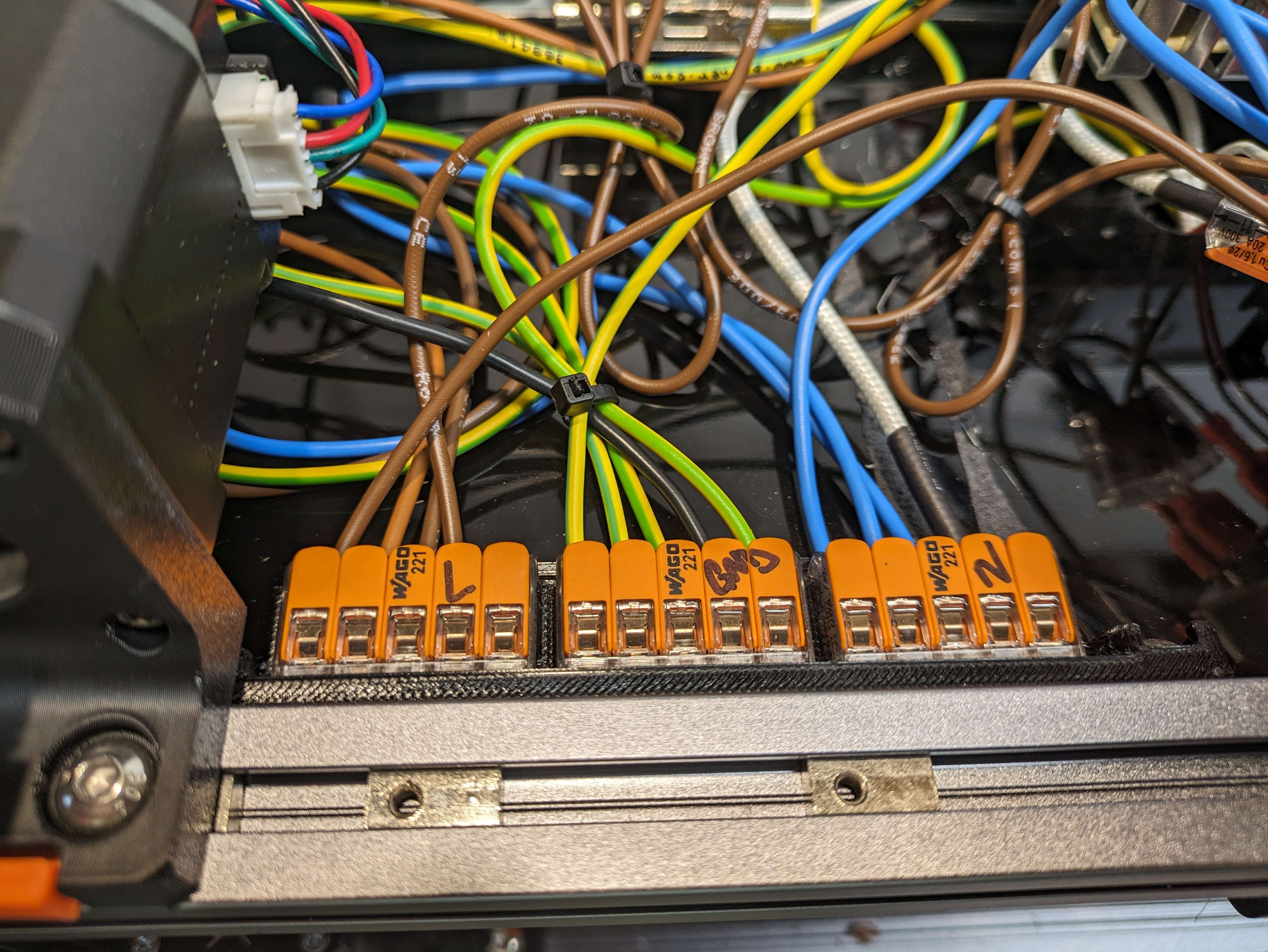
¶ Wagos Wiring
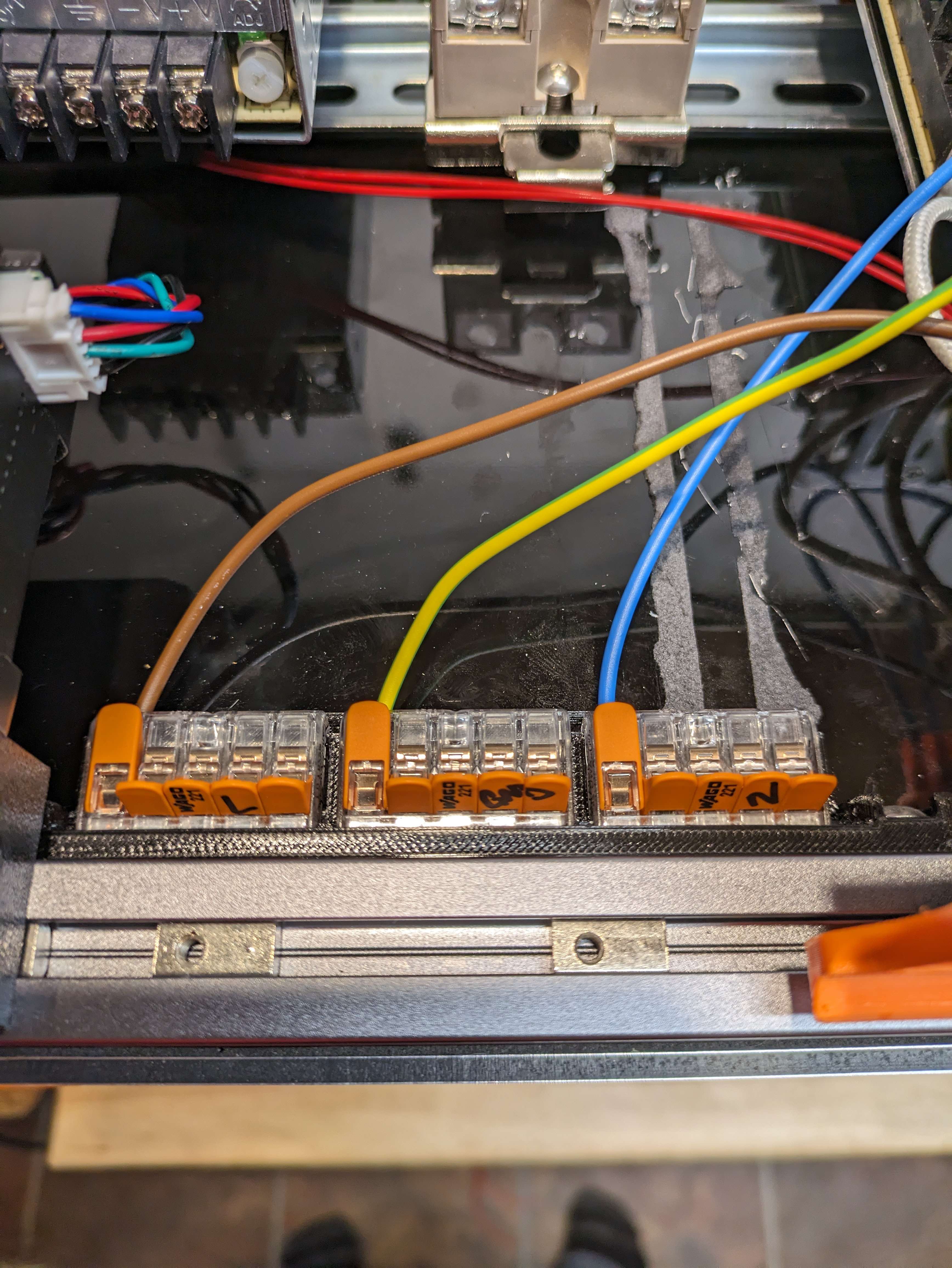
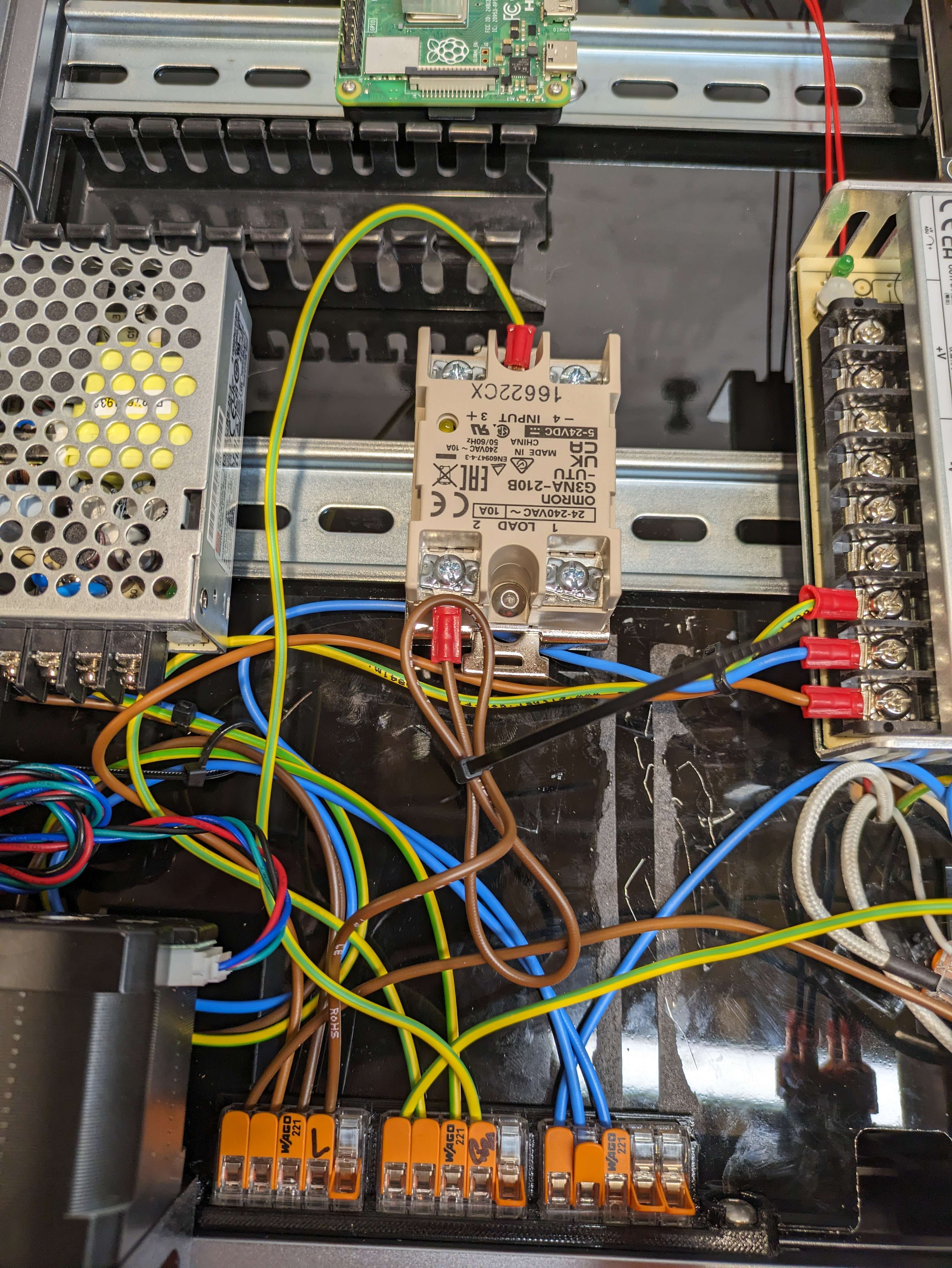
With them all plugged in, we are able to take the ends that are pre stripped and put them into the respective Wago's, Brown is L, Blue is N and Yellow/Green is PE/GND.
We will place them into the first spot on the wago. (Seen on Page 187.
I labeled my Wago's to keep them sorted and correct.
¶ Mains to PSU Wiring
In this section of the guide we will be looking at Page 188 from the voron manual, this is the space that we have all of the wiring that runs back to the wagos.
¶ Wiring 5v PSU
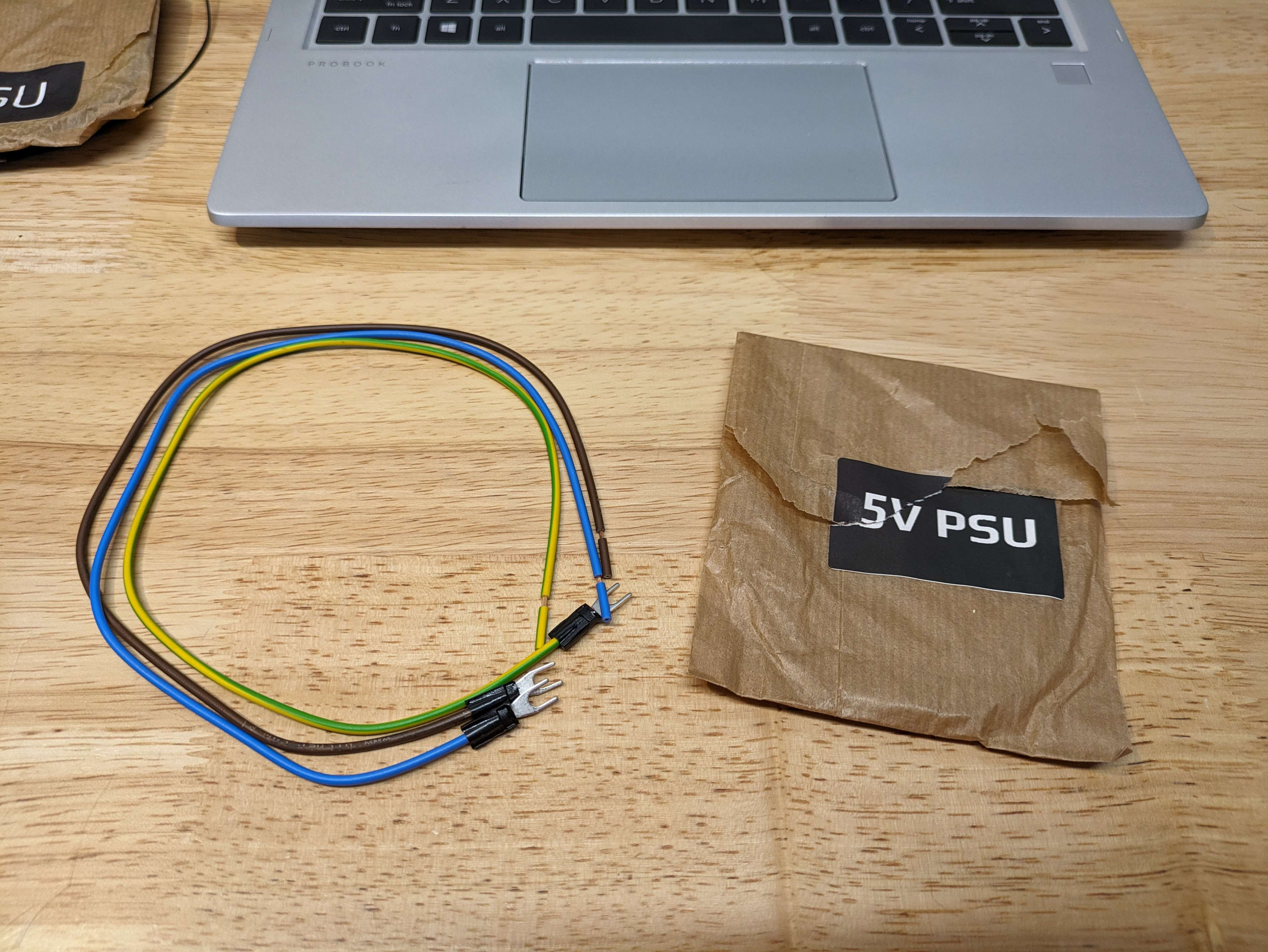
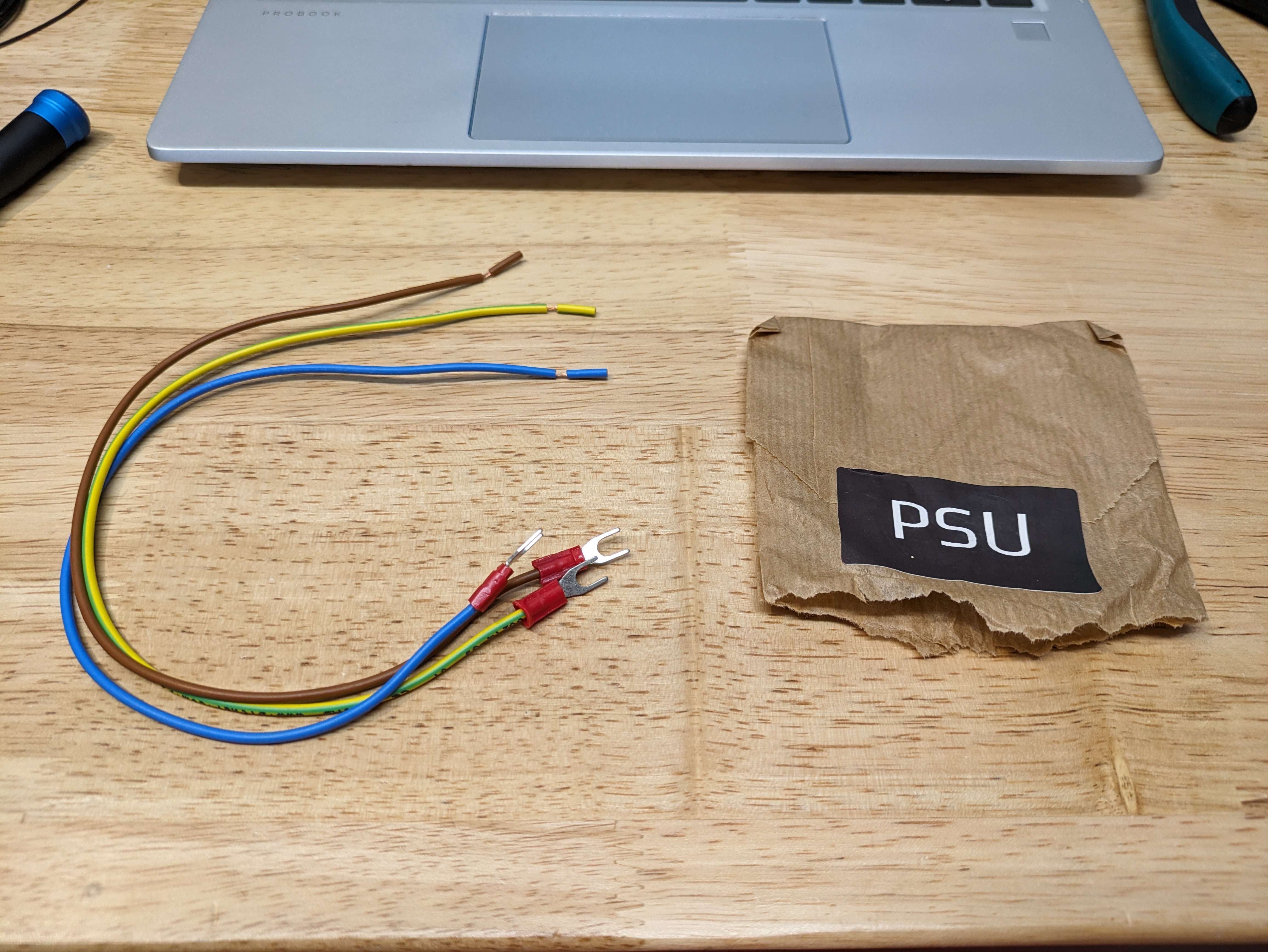
We can start with the 5V PSU, We will be using the following pack from the Linneo Kit.
-
First we will use the crimped ends and follow the same colors as before, the Blue wire with the crimped end will get terminated on the N position of the 5V PSU.
-
The Brown Wire with the crimped end will be connected to the L on the 5v PSU.
-
The Yellow / Green Wire with the crimped end will be placed on the Ground connector on the 5v PSU.
-
After all of those are connected to the 5v PSU, you will place the same color wires into the third port of the Wago with the same Color, N is Blue, L is Brown and Yellow is Ground.
¶ Wiring 24v PSU
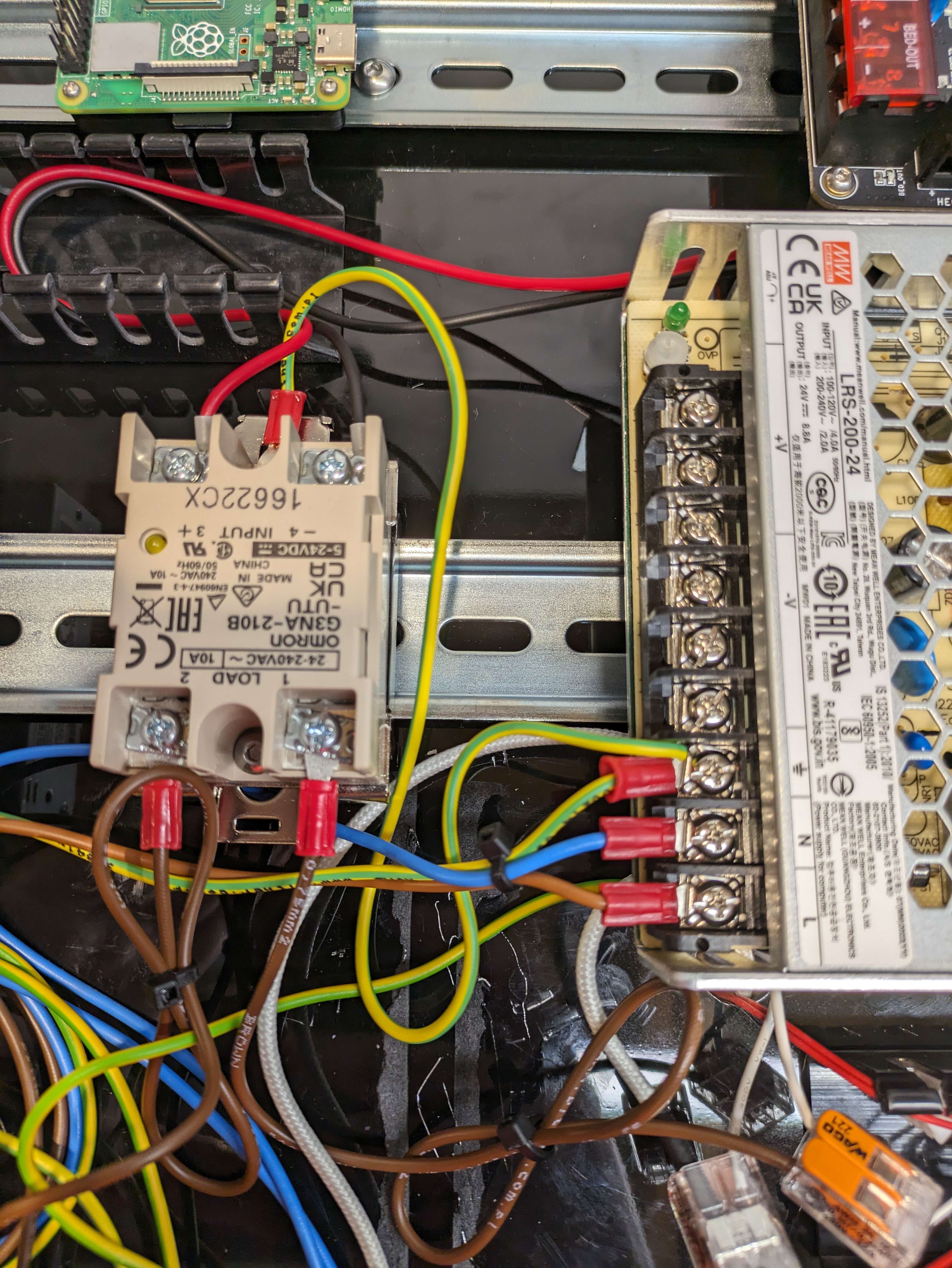
Now we can move down to the 24v PSU for the next part.
With the kit in the picture below we will wire in the 24v Power Supply.
With the PSU Wires you will follow the same instructions as the 5V PSU.
- First we will use the crimped ends and follow the same colors as before, the Blue wire with the crimped end will get terminated on the N position of the 5V PSU.
- The Brown Wire with the crimped end will be connected to the L on the 5v PSU.
- The Yellow / Green Wire with the crimped end will be placed on the Ground connector on the 5v PSU.
With all of the connectors are placed on the PSU we will add the Pre Stripped end into the second Spot on the wagos.
¶ Wiring The SSR
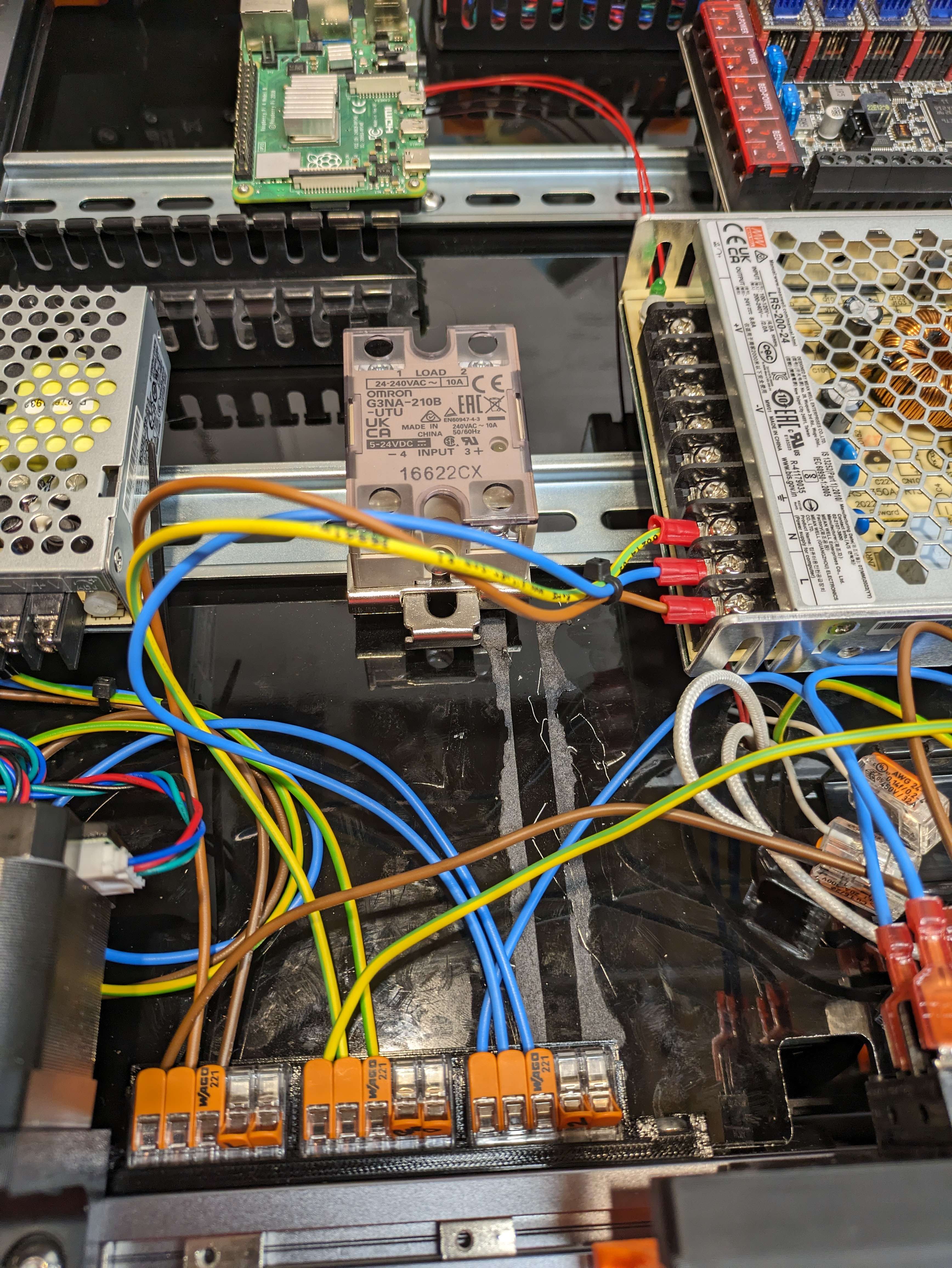
In This same image below you will see a Brown Wire that is connected to the #2 spot on the SSR. This is the line in from the L Wago that will be attached to the SSR for the Print bed in a later step.
Grounding the SSR is important so that it does not have any weird shorts or spikes in electricity for the Bed.
From either of the two attachment points to the Din Rail Plate you can add in the grounding wire.
You will use the package called Safety Ground: Frame / Din Rail.
you will use both of these in the next few steps.
We will take one of the wires and we will place the crimped end with the eyelet and we will place it under the one mounting point for the SSR to the Din Rail plate.
Per the Voron Manual you ground it too the Grounding point on the 24v PSU.
¶ Grounding The Frame
You will use the other Ground Wire from the Safety Grounds Package.
In the next few photos you will need a bit of sand paper to make good contact with your frame.
My Wire is Black because I moved my Grounding point because i had my under deck setup differently before this guide But yours should be Yellow/green.
Pick a spot that will reach within the length of the wire that you have for the ground and give the frame a sanding in a small spot on both sides of the extrusion opening. You want to be through the annodizing of the frame so that it makes good contact.
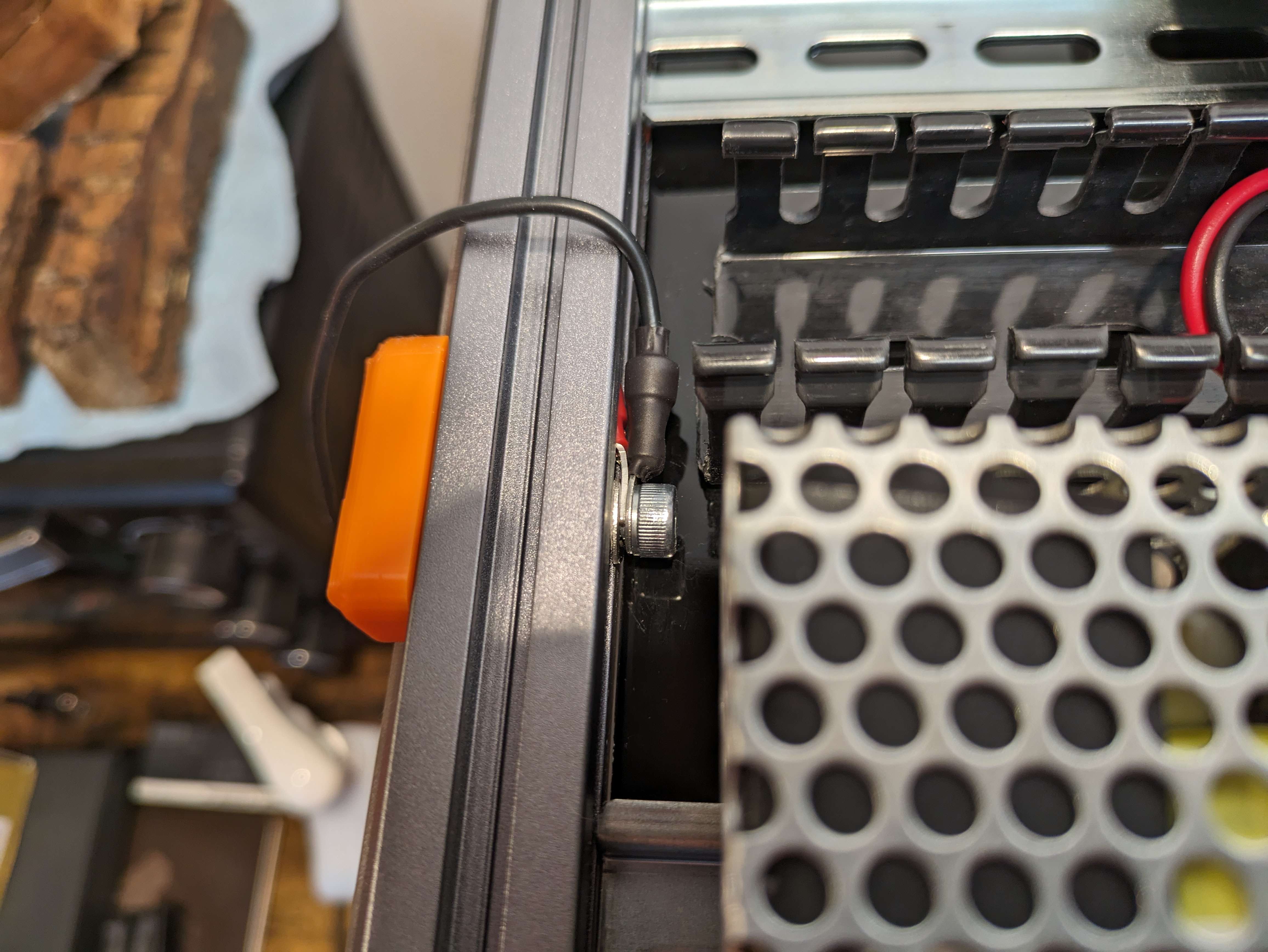
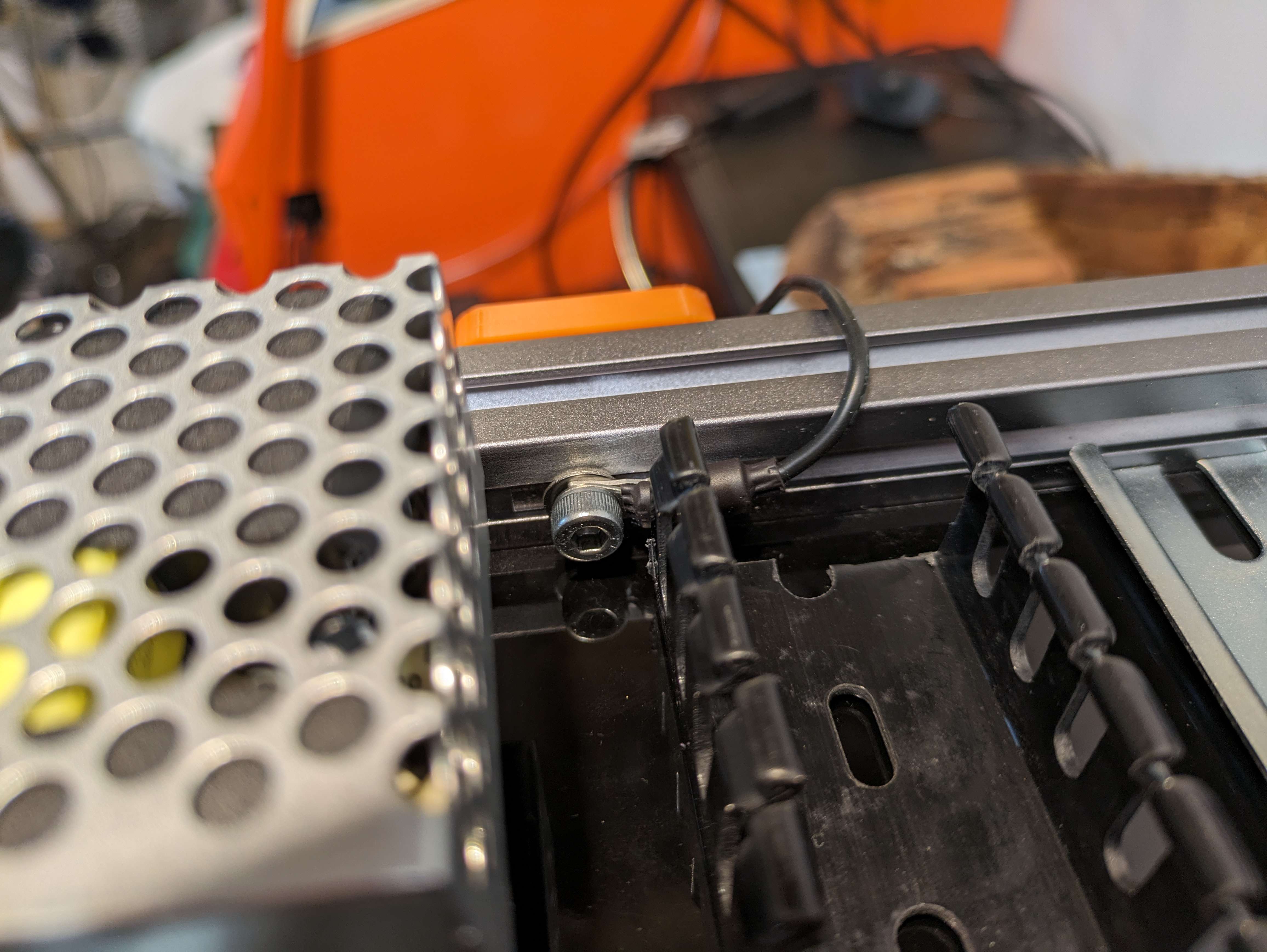
The Goal is to have good contact with the frame metal so that it can ground the frame so it does not build up any charge and then shock the system.
Once you have placed in a TNut and mounted the Frame Ground wire is secured to the frame with a m5 button head screw then you will be all set to place the wire in an open spot on the PE / GND Wago.
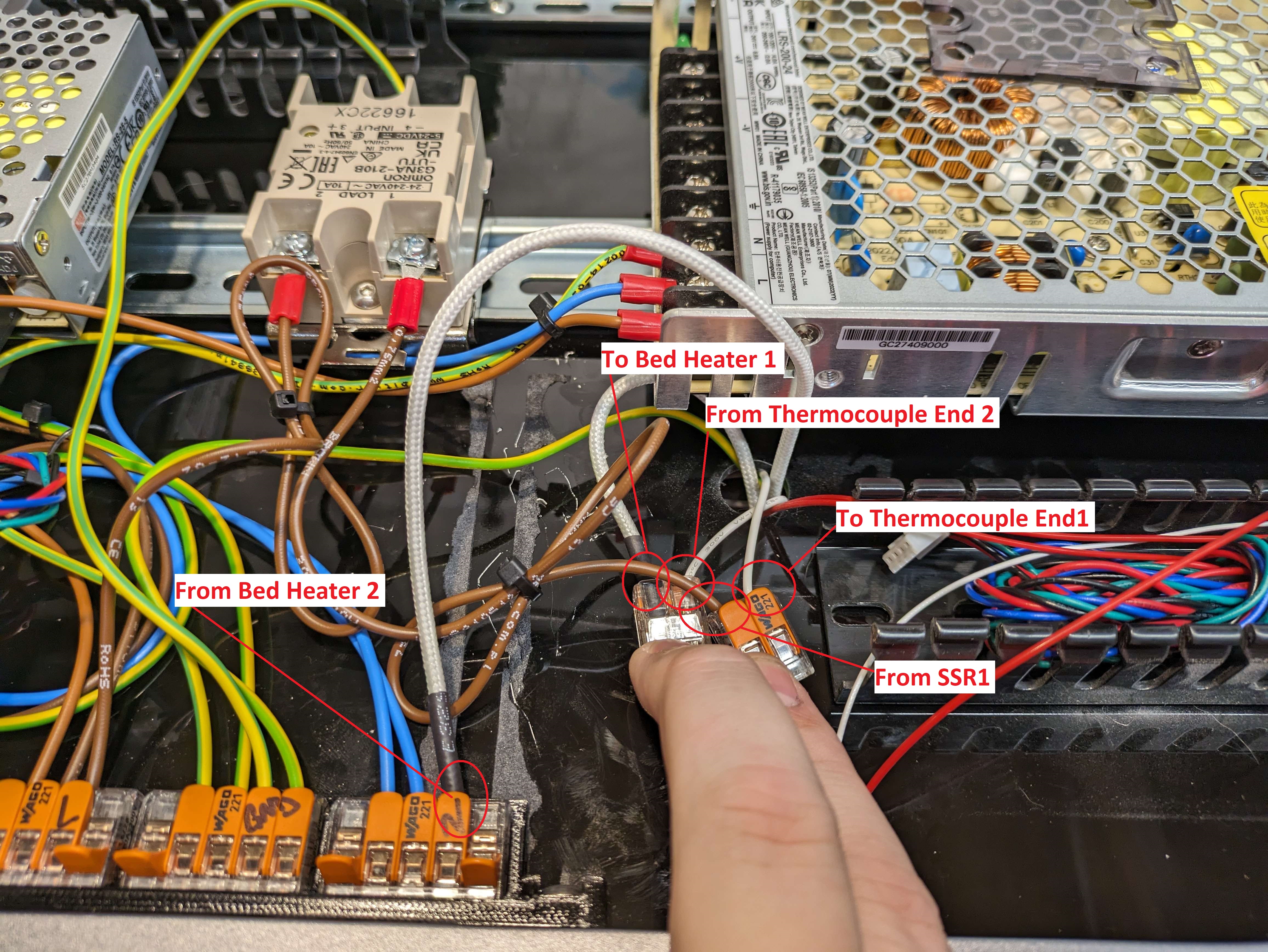
¶ Wiring the Printer Bed.
This portion of the guide will go over the printer bed wiring. It can get kind of confusing but I have made adjustments to the images to assit if anyone gets lost.
There are a few things that need set before you mounted your bed but its okay to go back and un-mount the bed before proceeding.
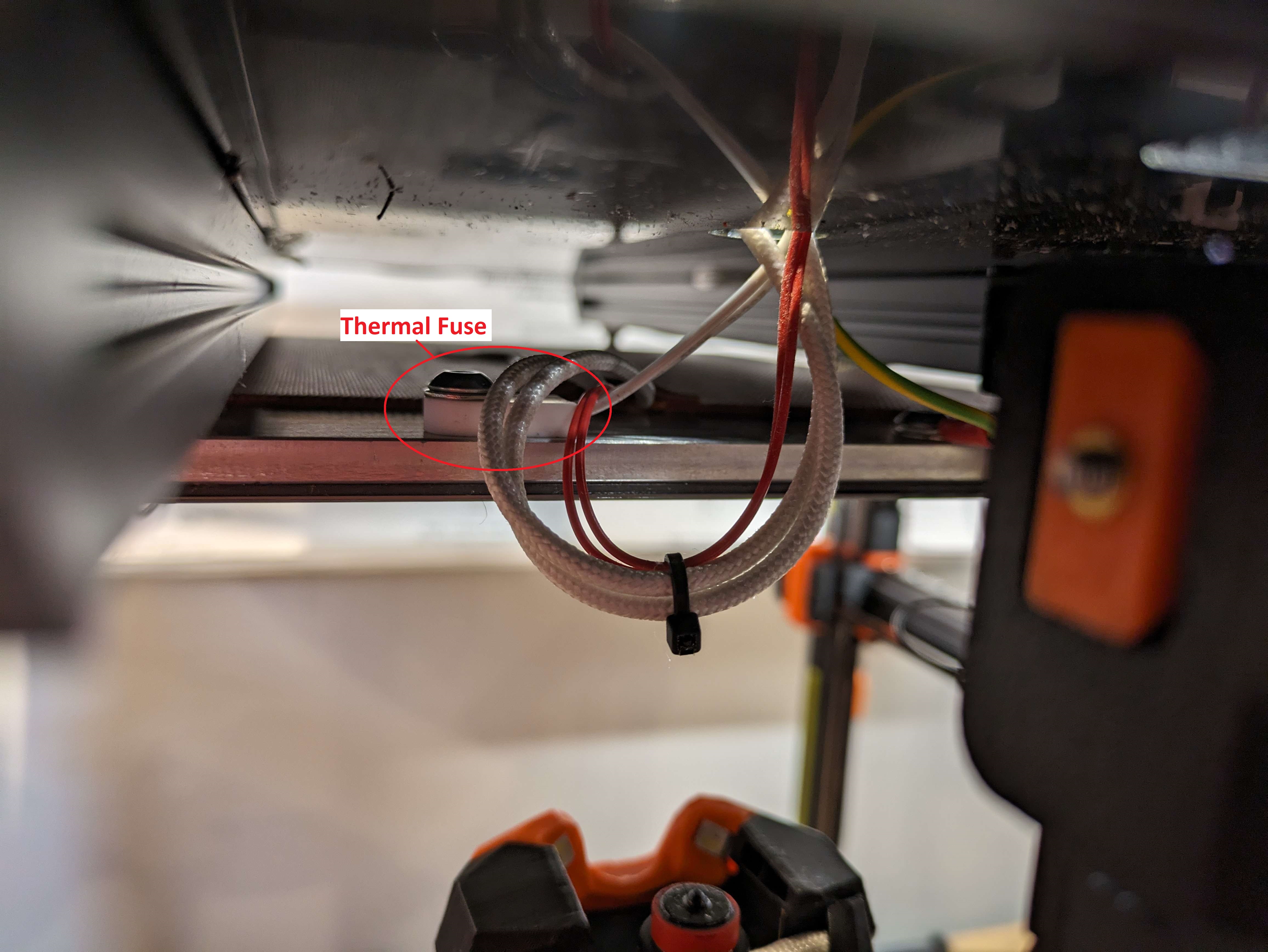
First is the Thermal Fuse and the Grounding Wire
You can see on the picture below that the Thermal Fuse and the Grounding Wire( Right side of image) are mounted to holes that are pre threaded on the Mandella Roseworks Bed. You can refer back to Voron Manual Page 56 / 57 for clarity.
These Red Wires coming from your heater pad are the Thermistor and the Bigger white wires are from the Heater.
I Pulled all of these wires into the Under Deck to make all the wiring in one place. There is a Wago Mod that you can do to leave all of the Thermal Fuse and ground wires under the bed if desired.
After you have all of the wires through the small hole and into the under decking we can start wiring up the Heated bed.
- First we will want to put 2 2Port Wagos onto the ender of the Thermal Fuse. This part does not make any difference as the fuse is not a directional item like a capacitor, it works in both directions.
- Second, We will want to wire in The SSR to 1 of the Wagos that has a thermal Fuse line in it.
- Third, Take one of the White Thick Bed Heater wires and place it into the remaining Wago that is connected to the Thermal Fuse.
- Take the remaining Heater bed wire and place it into an open spot on the N 5 port wago that is connected to the N mains line.
- There should be a Yellow and Green Wire that is coming through the hole, you can place this in any open spot on the 5 port Wago by the Power Inlet.
What this is doing is creating a path for the electricity to flow, Once the Controller board tells the SSR to heat the bed, it will open the Load ports from the connector 2 to the Connector 1, Then Connector 1 will go through the Thermal Fuse, The Thermal Fuse stops the bed from over heating and causing any un needed random fires. Once it goes through the fuse then it goes to the heater to start heating. The last heater wire is connected to N because then it completes the ciruit.
If you quickly glance at page 189 in the voron manual this will have a dark blue line and a ground wire and N wire for the printed bed, you have to scroll backwards to page 184 and this will show you the rest of the wiring for the printer bed heater.
¶ Verifying the Connections (Optional)
This is not a needed step but something that can make you feel better about your connections especially if you are using Main Voltage to power things.
In the next few videos I will be using a multimeter to check various connections on the wiring that we just completed. These videos will download to your computer to play but are not that big in size.
You will need to set your multimeter in Continuity mode, this will make the multimeter beep when it completes the circuit.
What this will tell us is that all of the connections that were made inthe Wago connectors are working as intended.
Grounds Check: In this video I am Checking 3 main grounds.
- 1 Ground from 24v PSU is connected to the Din Rail at the SSR.
- 2 The Ground Connection from the 24V PSU to the 5v PSU.
- 3 The Ground Connection from the 24V PSU to the Ground to the Frame.
The Two that i missed: - 4 Checking the Ground from the 24v PSU to one of the Hidden Connections for the frame.
- Checking the Ground pin from the Power Inlet to the 24V PSU.
L Connections Check:
- Checking from the L Connection on the 24v PSU to the L connection on the 5v PSU.
- Checking the L Connection from the 24v PSU to the SSR,
- Verifying that the SSR is not letting the power through without the controller telling it that is why you see me move it from one to the other and then back to make sure.
lconnectionscheck.mp4
N Connections Check: 2 Videos.
- Checking the N Connection from the 24v PSU to the 5v PSU,
- Checking the N Connection from the 24v to the ground for the frame to make sure it is not dead shorting on the frame.
- Checking the N Connection on the 24v PSU to the connection that leads back to the SSR port 1. Since it is connected on the one end it can complete the connection through the fuse and heater.
n connections 1.mp4
n connections 2.mp4
¶ Controller & PI Wiring.
Lastly we have come to the final section, The wiring for the control Board and the Raspberry Pi.
We will utilize the last package from the linneo Wiring Kit.
We will be looking at Page 190 of the Voron Manual.
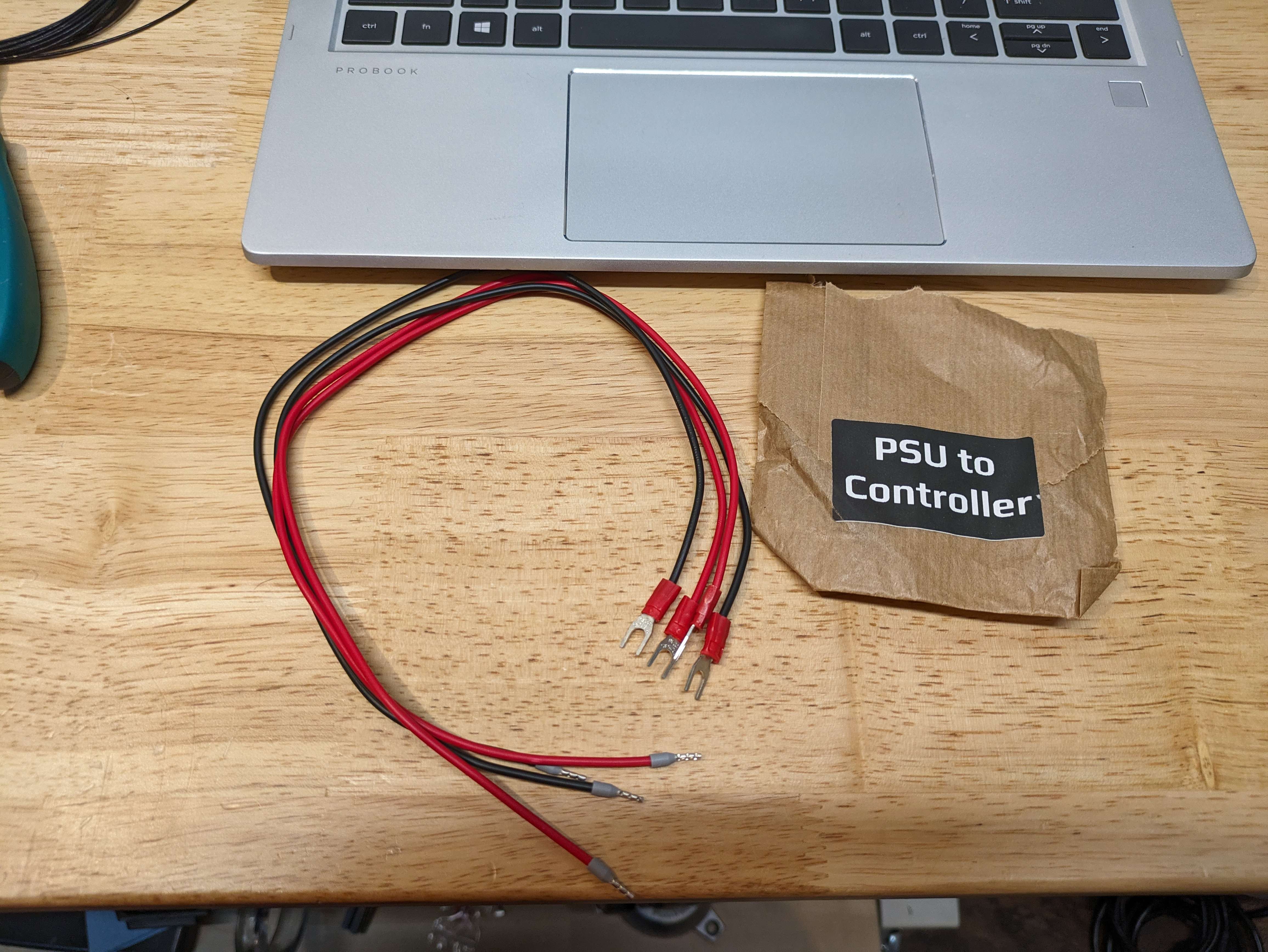
We will start with 1 red wire and 1 back wire.
There is one end that is crimped with a ferule and one end with a fork connector.
You will take the Fork end of the red wire and place that into the V+ from the 24v PSU.
Take the Fork end of the Black wire and place that into the V- from the 24v PSU.
The Voron Manual calls for 2 jumpers to be created and placed at the controller board from the Poer in to the Motor Power sections.
To Create these find some spare wire from the kit, does not matter what color. But you need about 2 inches, you will use the wire strippers to take off about 5mm of outer wire to find the inner wire. Once that is done twist the wire end in one direction to make sure it is solid and secure. Then Place the jumper in the Corresponding positive and negative from Power to Motor Power.
- Do this for both the positive and the negative.
From this point we will take a spare black, brown, or yellow wire and will be placing a V- jumper to the v- of the 5v PSU.
I made a little wire connector out of the spare wire that was sent for the linneo under the deck wiring kit and crimped on ends to the wires to create a little connector for the PI to be wired up without having to mess with the pin ends or finding the correct connectors for the GPIO pins.
From the 5v PSU I ran a wire to the connector from V+ and then placed it in the first spot on the connector. Then I did the same for the 5v PSU from the V- for the Ground this was placed in the third spot.
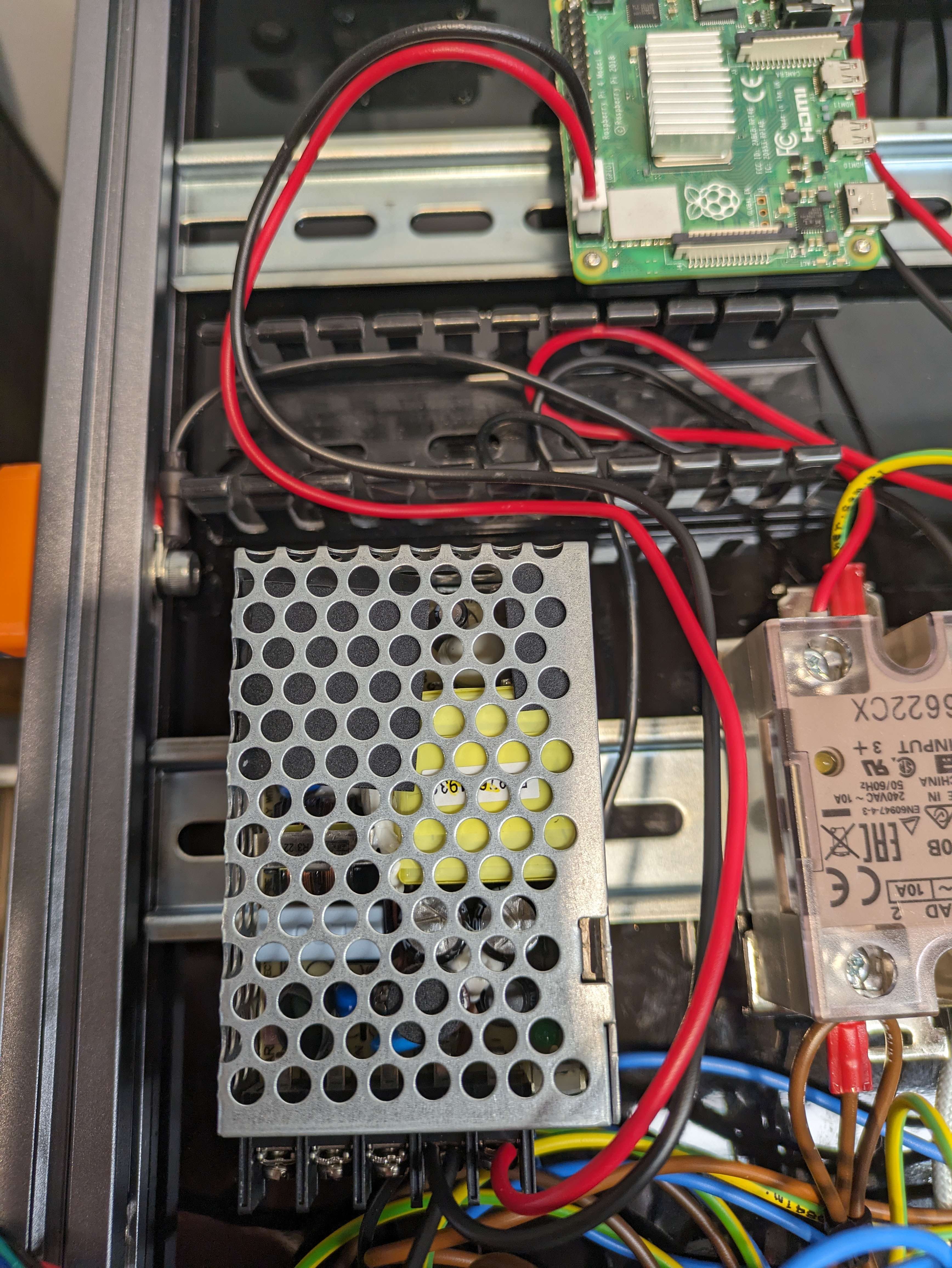
Then I connected this to the PI for power from the GPIO pins.
You can see all of the steps from this one photo.
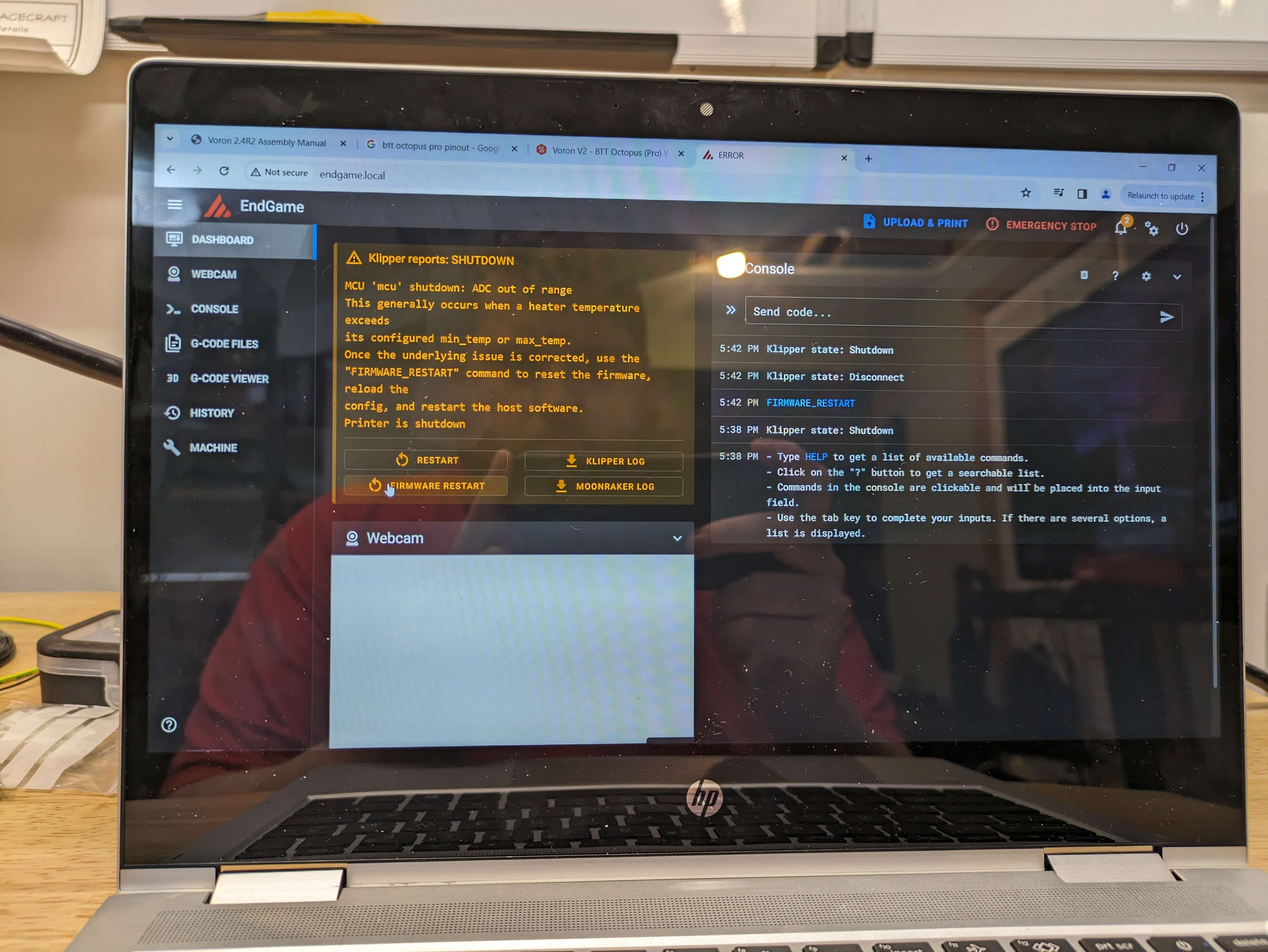
Once you have this all complete and you feel confident and have double checked your work to the Voron Manual and this Guide you can flick on the power and see the MCU and Pi Come online.
¶ END
That will conclude the wiring guide for the Linneo Under The Deck Wiring Kit.
You can take some time to clean up the wires and zip tie them to make them tidy, While the printer is off please, don't want someone shocking themselves.
There are Wiring Ducts that can assist in making the whole wiring look way cleaner.
Wiring Ducts
There is also Split Wire Sleeveing that you can buy to make the runs between the connections look clean as well.
If you have any questions, suggestions or need assistance feel free to reach out in discord we have many people willing to assit and a ticketing system if you cannot seem to find the right answers.