¶ Voron Tap OptoTap v2.4.1 PCB by Linneo
For the most current information (including assembly instructions) see the Voron Github.
Note: This page covers the latest version of the OptoTap PCB v2.4.1. Here is a link to the documentation for the v1.0 and v2.1
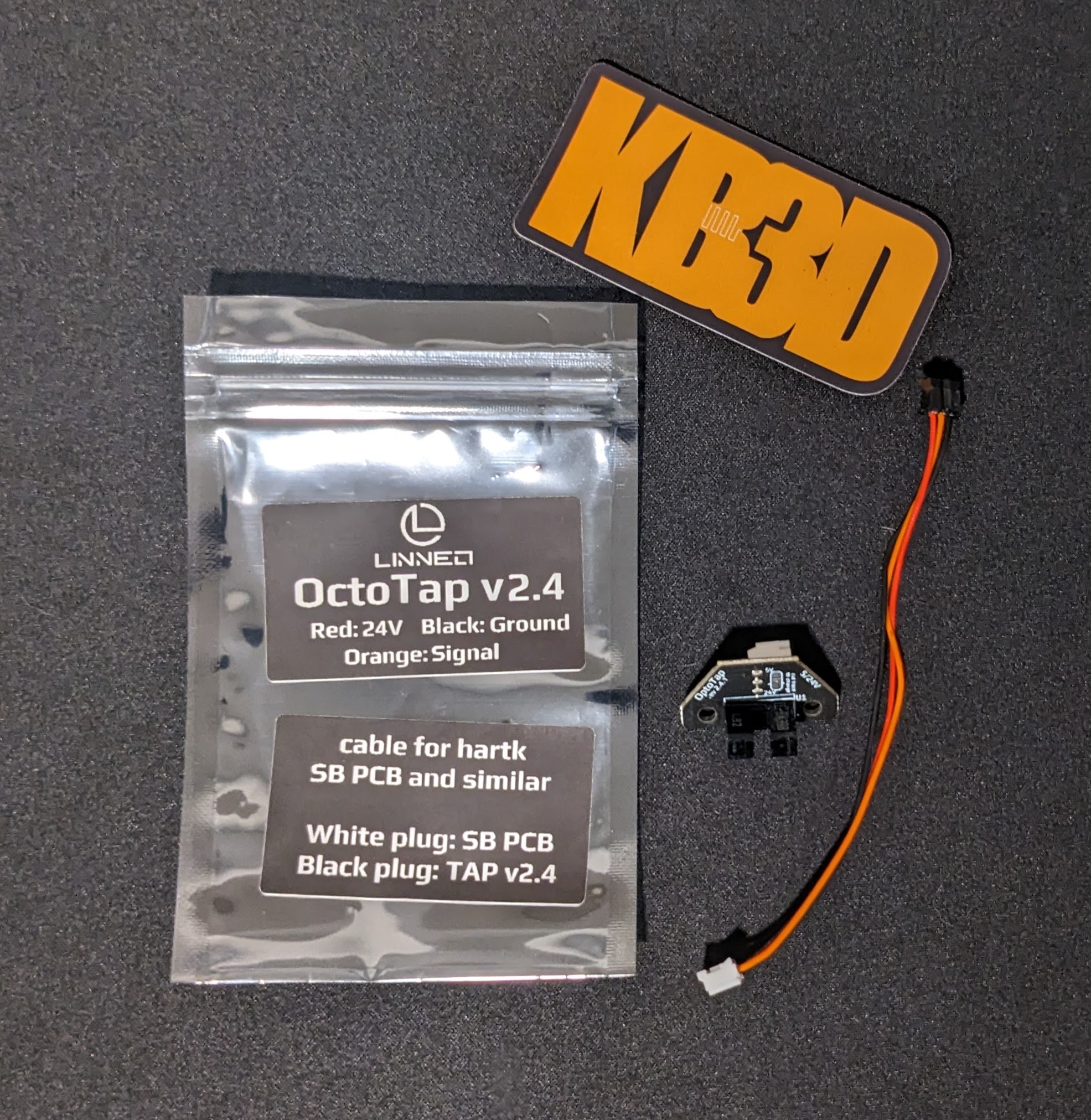
This sensor is designed to work with any 24V probe port, which greatly simplifies the installation for most users. If you do need to use a 5V probe port (ie many CAN toolhead boards) follow the instructions at the end of this page.
Note: the wire is directional, the black connector connects to the TAP PCB, and the white wire connects to your Toolhead PCB.
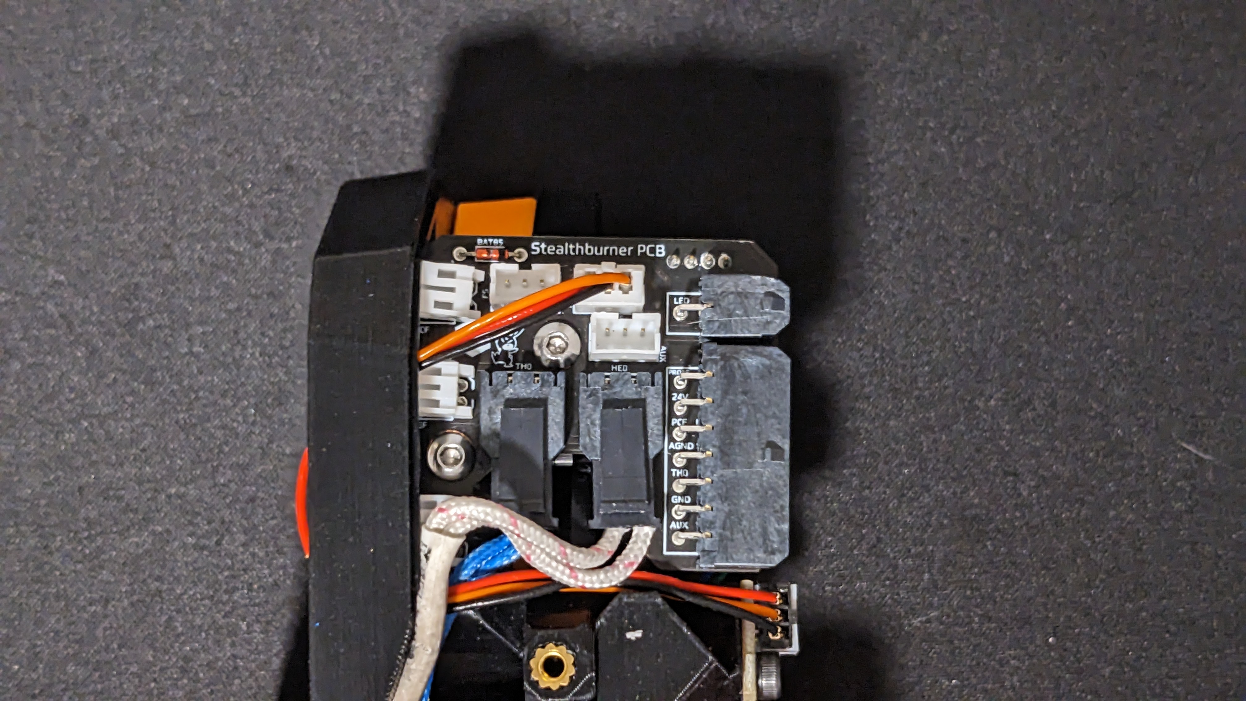
¶ Stealthburner 1pc Toolhead Board rev 3
For the Hartk 1pc rev3 board, you can use the right Probe port.
¶ Stealthburner Toolhead Board (1 piece Rev4)
For the Hartk 1pc r4 board, you can use the right Probe port.
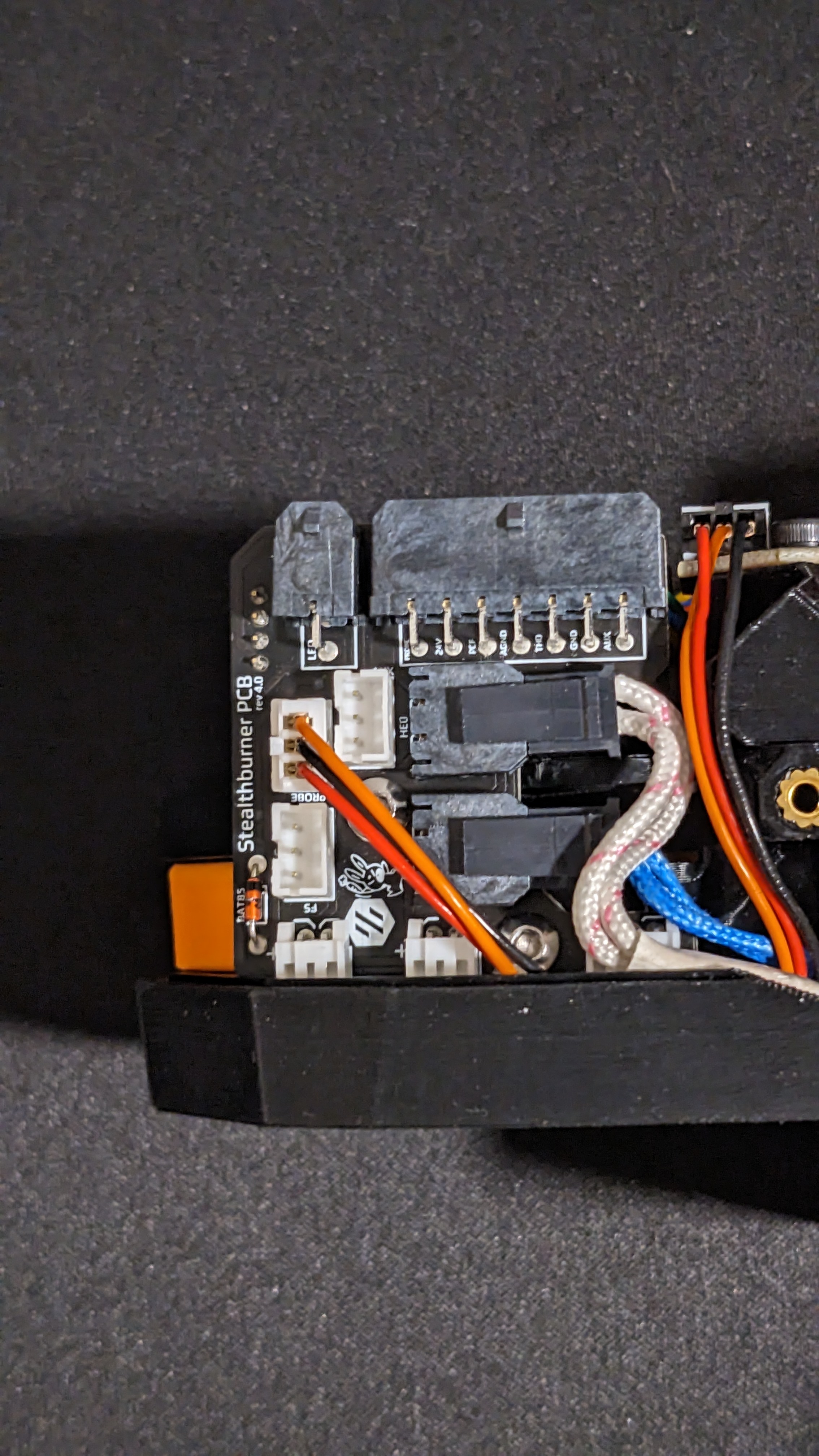
You can continue to follow the Voron TAP Klipper instructions.
¶ Stealthburner 2 Piece rev 2 Toolhead Board
With the Hartk 2pc rev2 board, you can again use the right Probe port.
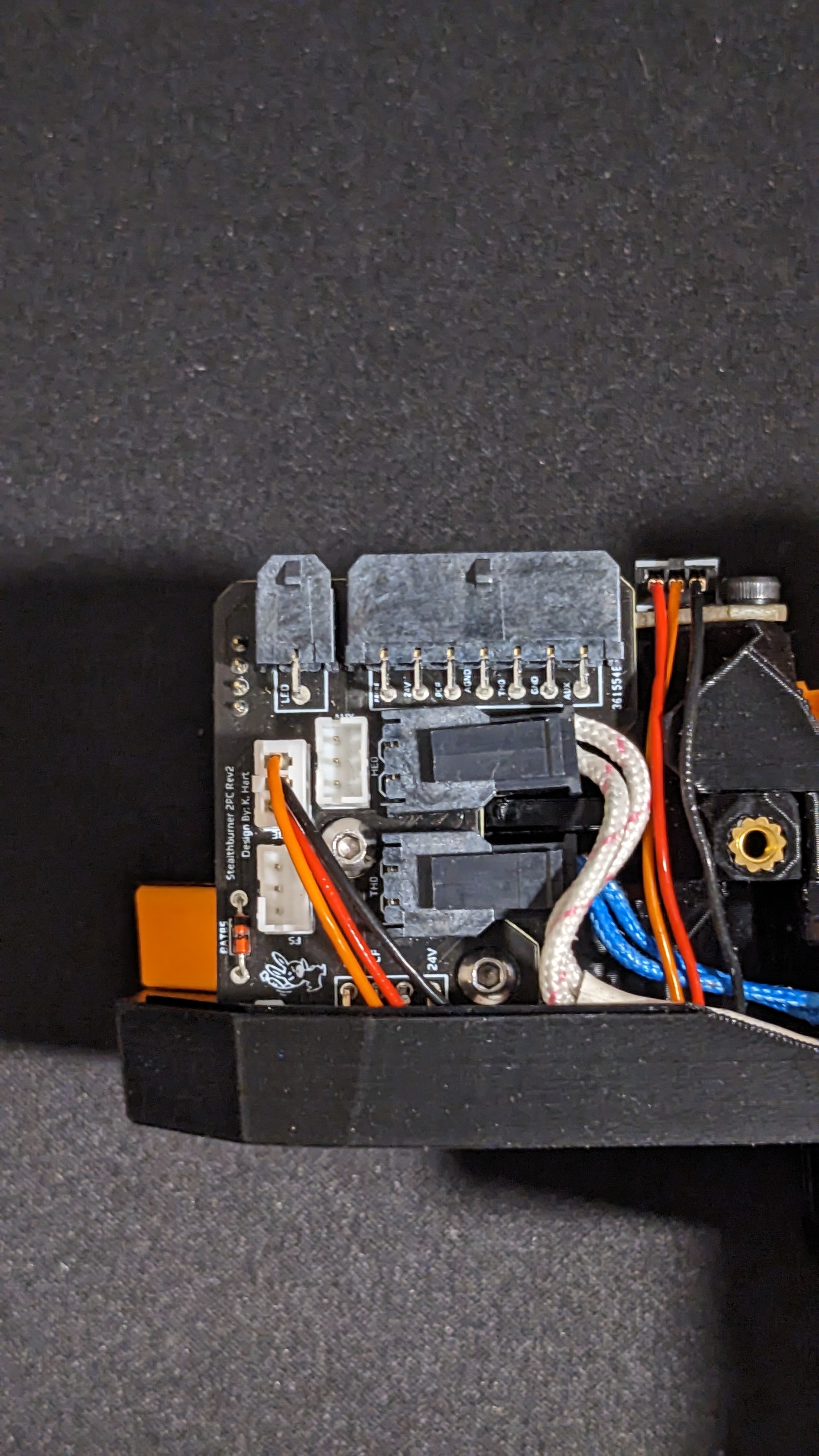
You can continue to follow the Voron TAP Klipper instructions.
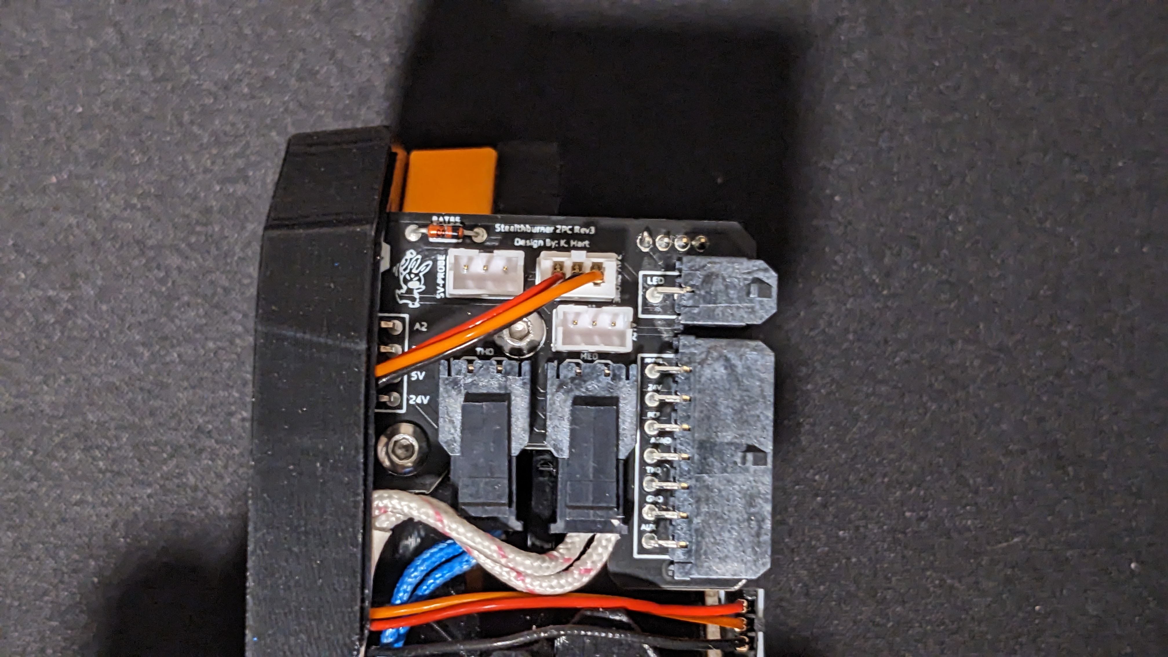
¶ Stealthburner 2 Piece rev 3 Toolhead Board
With the Hartk 2pc rev3 board, you can again use the right 24v Probe port (note if you need to use the 5V probe port, you can modify the OptoTAP PCB to support this, follow the instructions at the end of this page).
You can continue to follow the Voron TAP Klipper instructions.
¶ Directly Wired
If you are not running a Stealthburner Toolhead board, you can reuse your existing wiring, but will need to re-terminate the provided harness to connect to your existing wiring. Ensure you follow the wiring colors as provided blow.
Once you are done wiring, you can follow the Voron TAP Klipper instructions.
¶ 5V Conversion
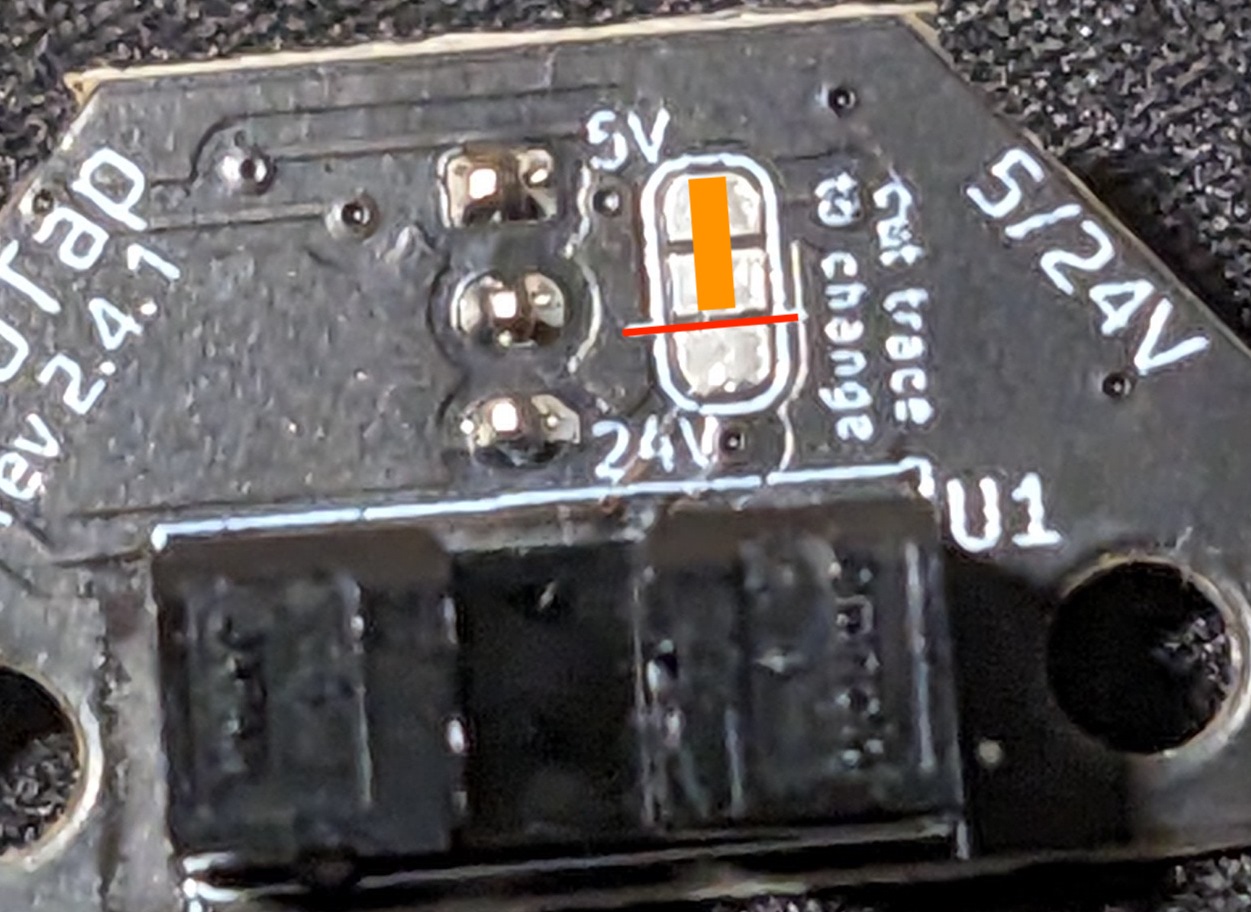
While not absolutely necessary, as the PCB has a buck converter to reduce the voltage, if you feel the need to convert your board to 5V, you can cut the trace on the back of the PCB as shown in Red, then bridge the 5V and center pin with solder, as shown in Orange.
¶ Wire color assignments (for reference):
Red = 24V In
Black = GND
Orange = Trigger Signal