¶ Linneo LED Resistor PCB
This guide steps you through the installation of the Linneo LED Resistor PCB.
Some RGB LED's require an additional resistor to avoid erratic behavior. This PCB from Linneo is designed to offer a simple and easy way to rectify this issue.
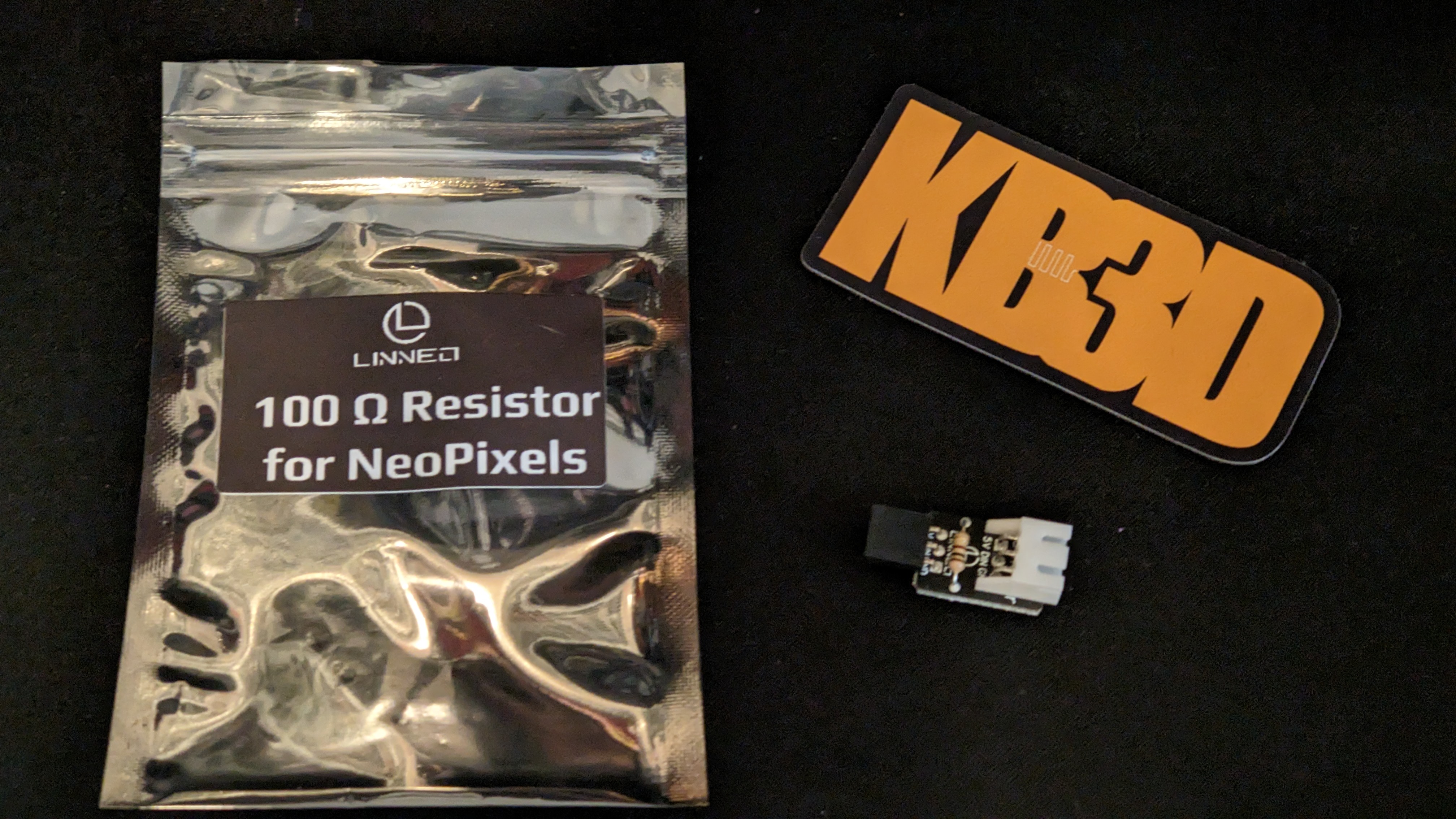
This PCB plugs right into the Dupont connectors on your Octopus MCU, though you will need to re-terminate your wiring from Dupont to JST.
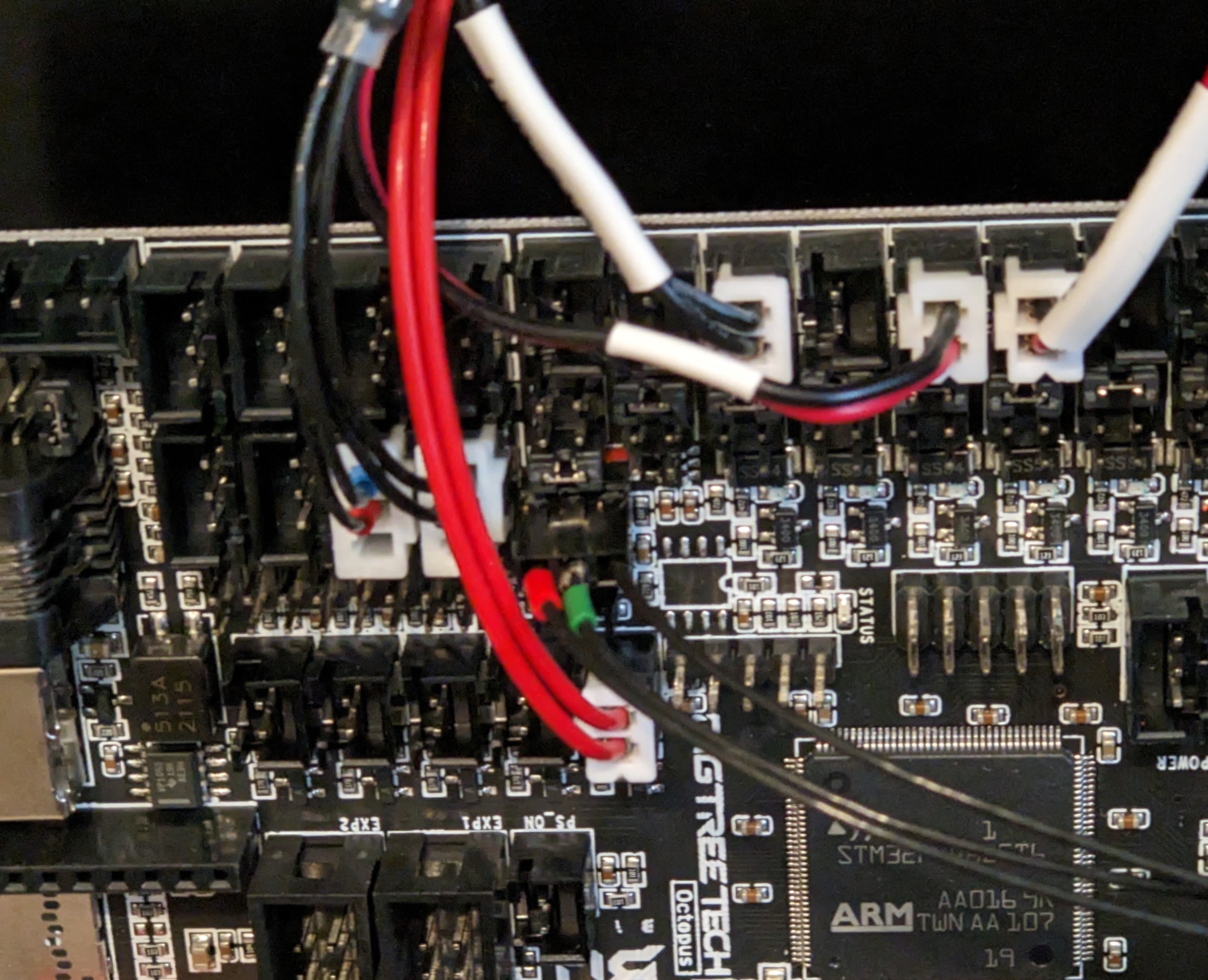
First, remove your existing Dupont connector, if your wiring isn't labeled, ensure you label the wires before removing the connector.
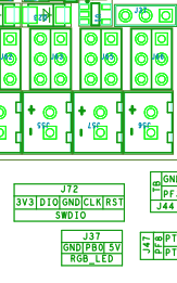
Per the BTT Octopus PIN diagram, 5v is towards the Endstop connectors, Signal is the middle and ground is at the other end.
Then plug in the PCB.
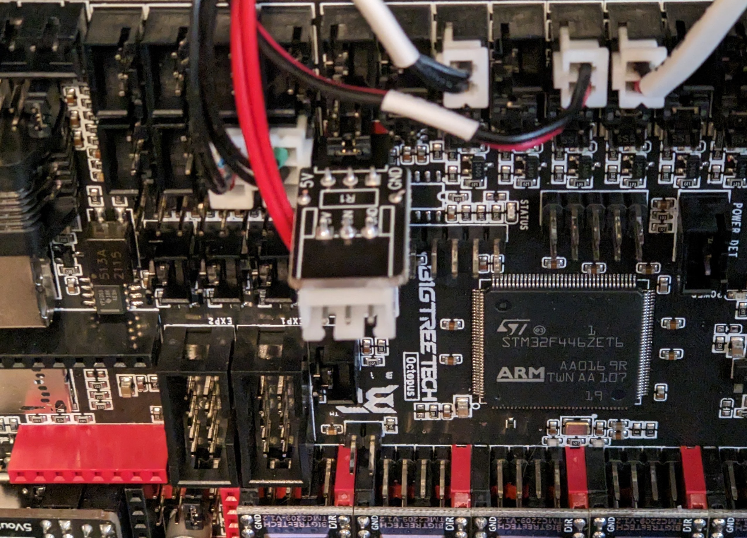
And then you re-terminate your wiring to JST.
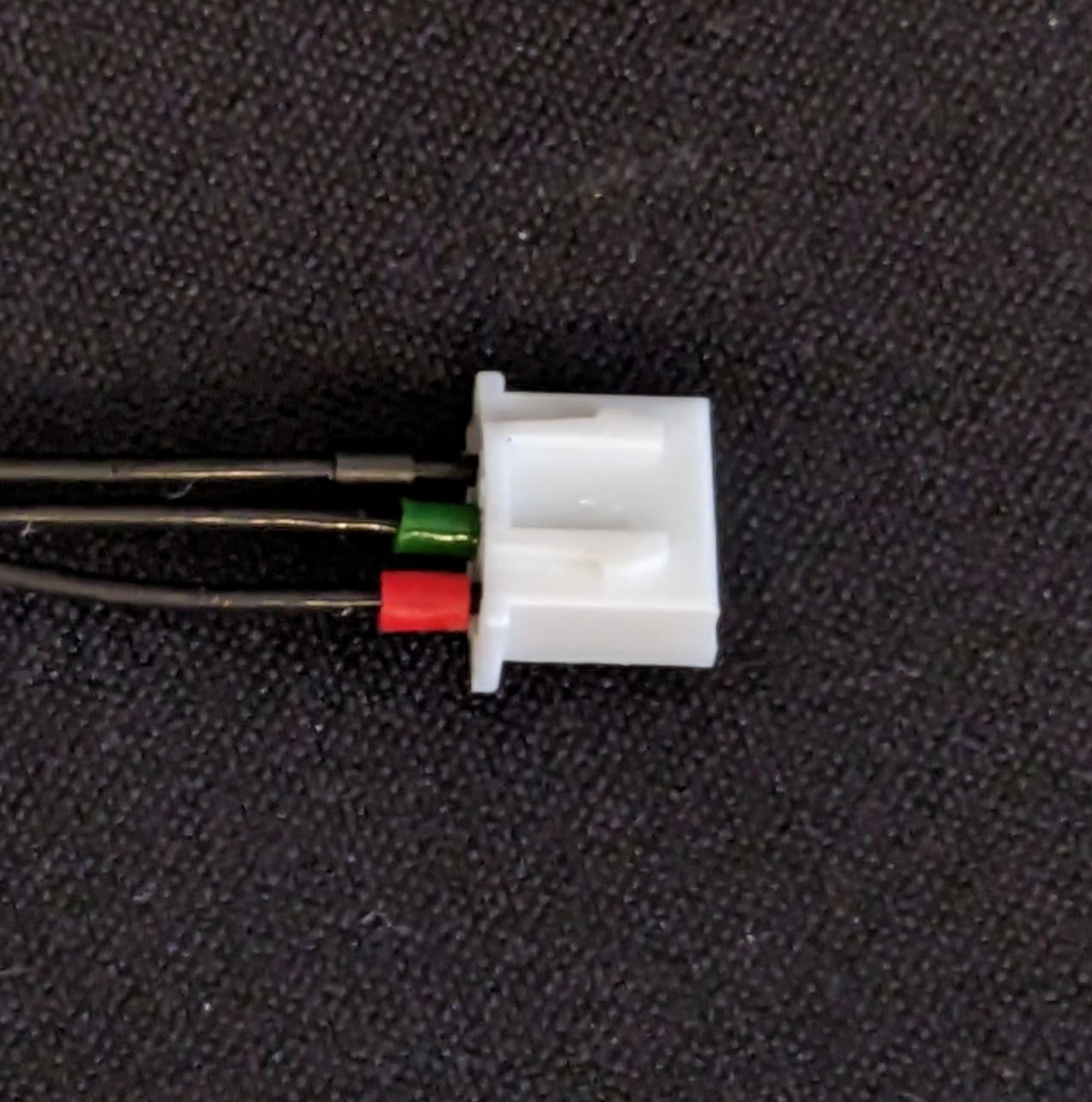
And then plug it into the JST socket on the PCB.
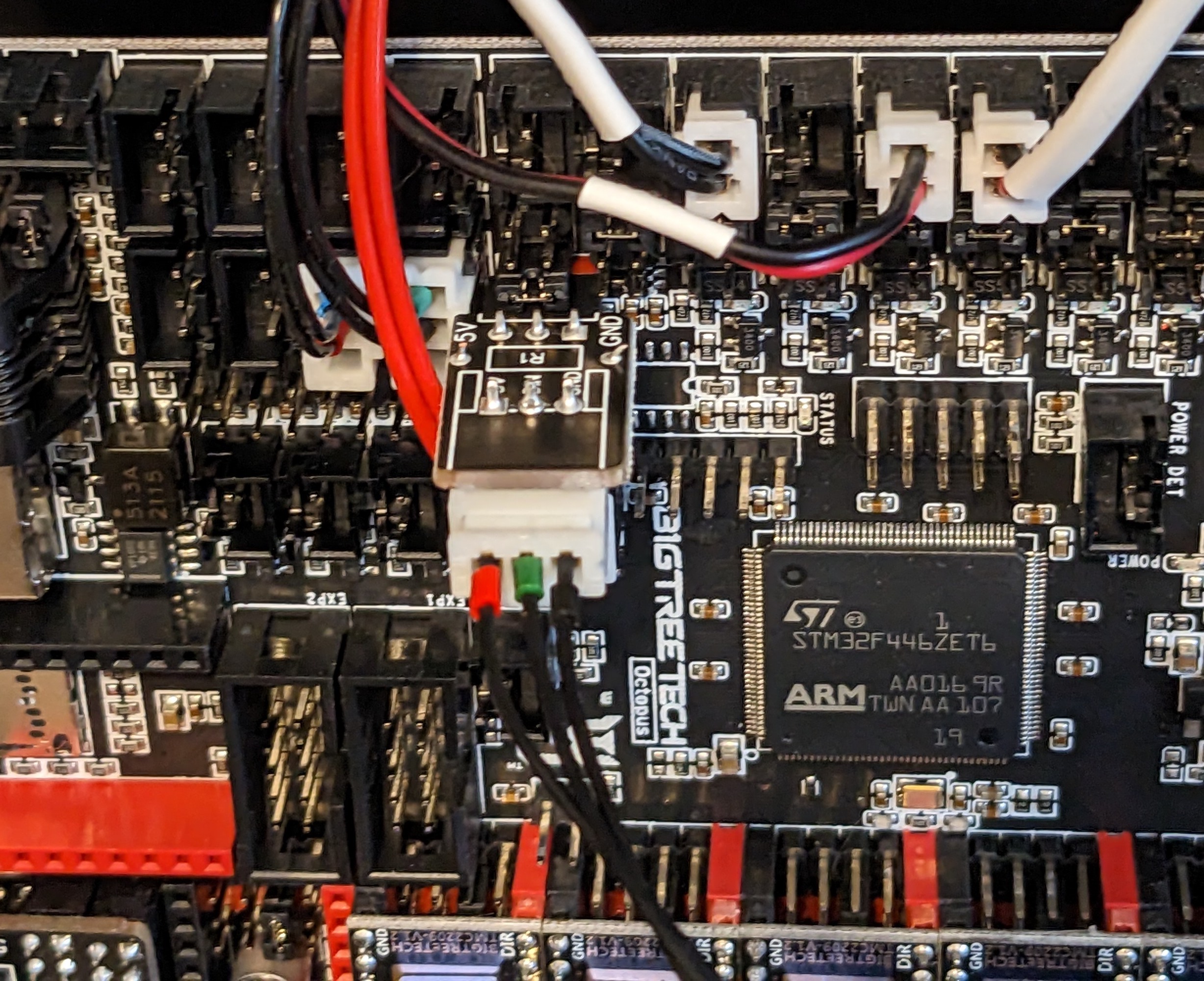
As long as your RGB LED's were working previously, you do not need to do any configuration changes. If you are adding RGB LED's for the first time, check out our Wiki for the Linneo RGB harness.