¶ Voron Stealthburner 1 Piece Toolhead PCB
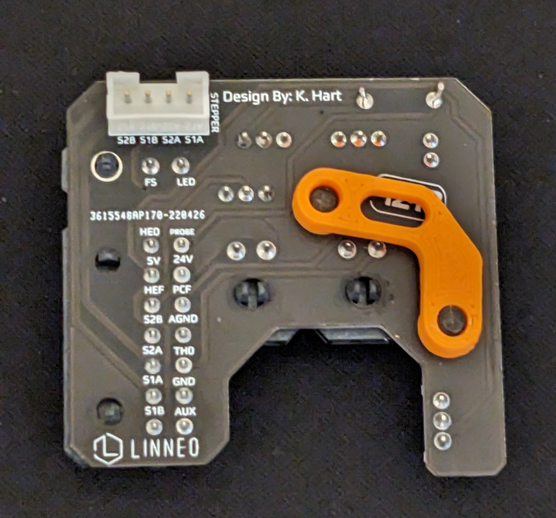
This guide steps you through the wiring and installations for Linneo's 1 Piece Toolhead PCB from hartk.
For the 2 piece Toolhead PCB, use this link.
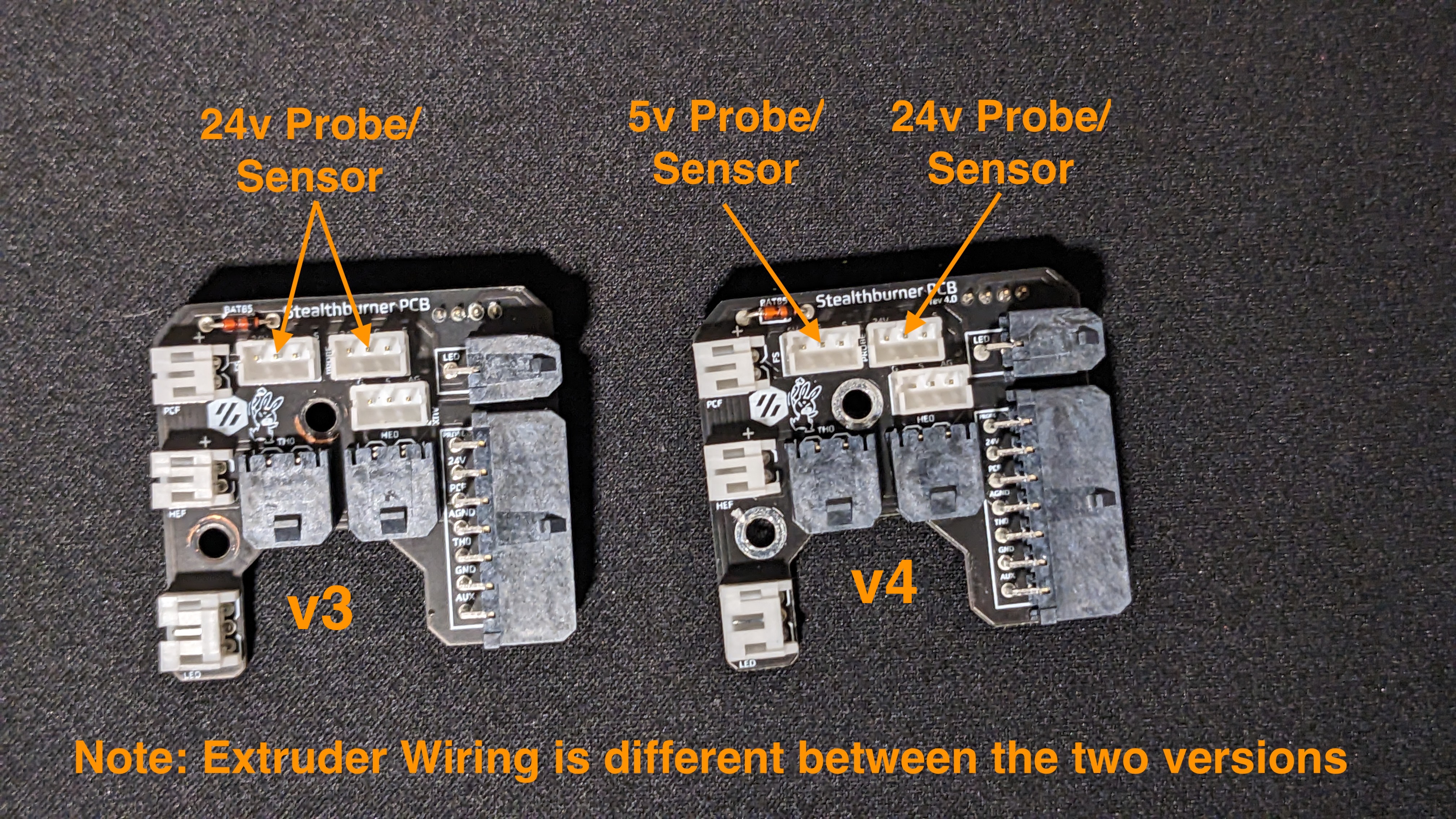
NOTE: This page covers both the v3 and v4 versions of the 1 Piece Toolhead PCB. We will flag differences where they apply.
To wire the 1 piece Stealthburner Toolhead PCB, you will need the following connectors…
MCU Connections
2-pin Vertical Molex Microfit 3.0
HotEnd/Thermistor
Fans/LED's/Probe/Stepper
The Fans, LED's, Probe and Stepper use JST-PH connectors, which are smaller than a normal JST-XH. Our JST-PH mini kit has all parts needed.
2x 2-pin
4x 3-pin (two are optional)
1x 4-pin
You will also need the PCB Spacer, and two M3x8 SHCS and to ensure you put the appropriate heatsets in your SB toolhead, as per Page 13 of the Stealthburner Manual.
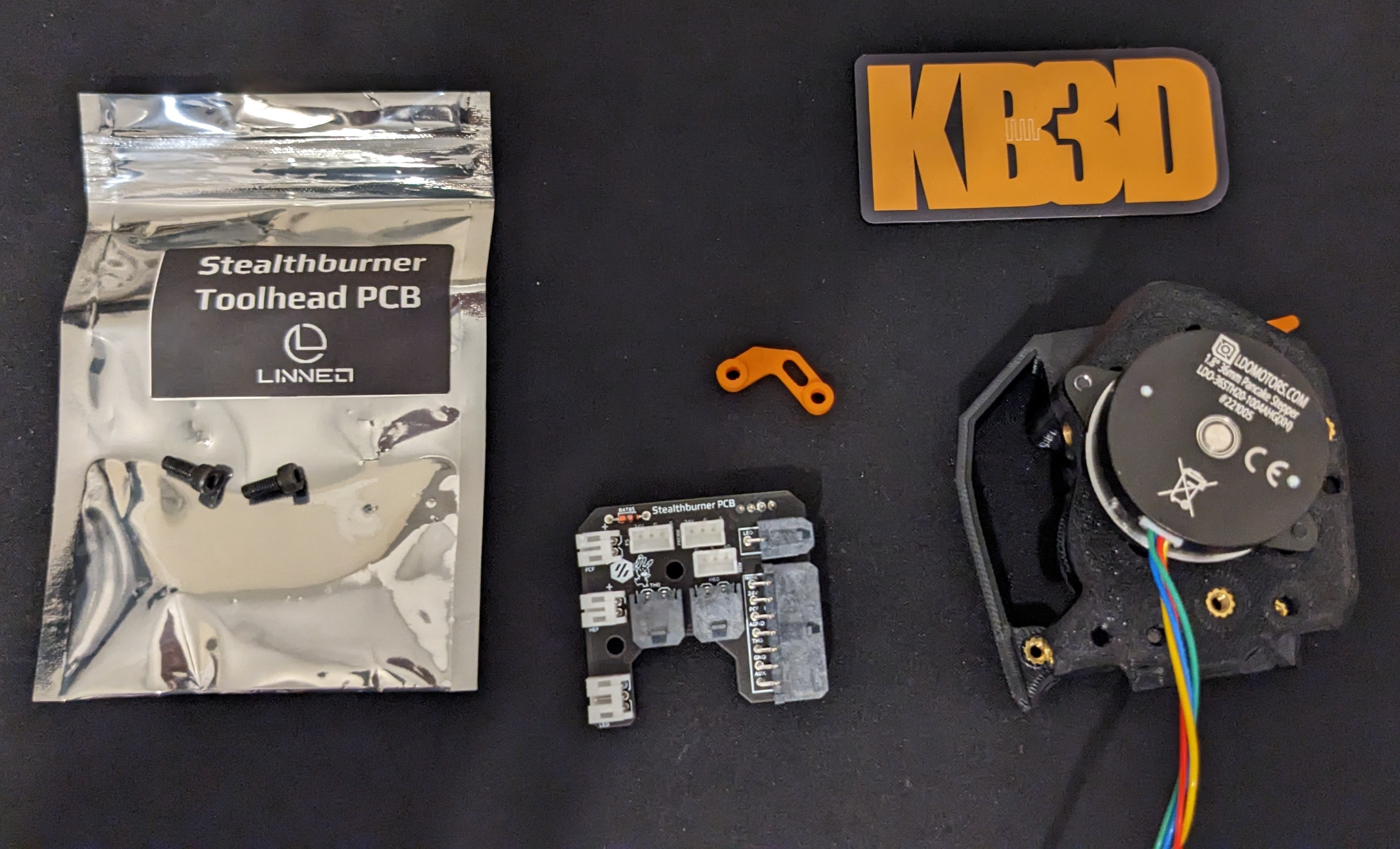
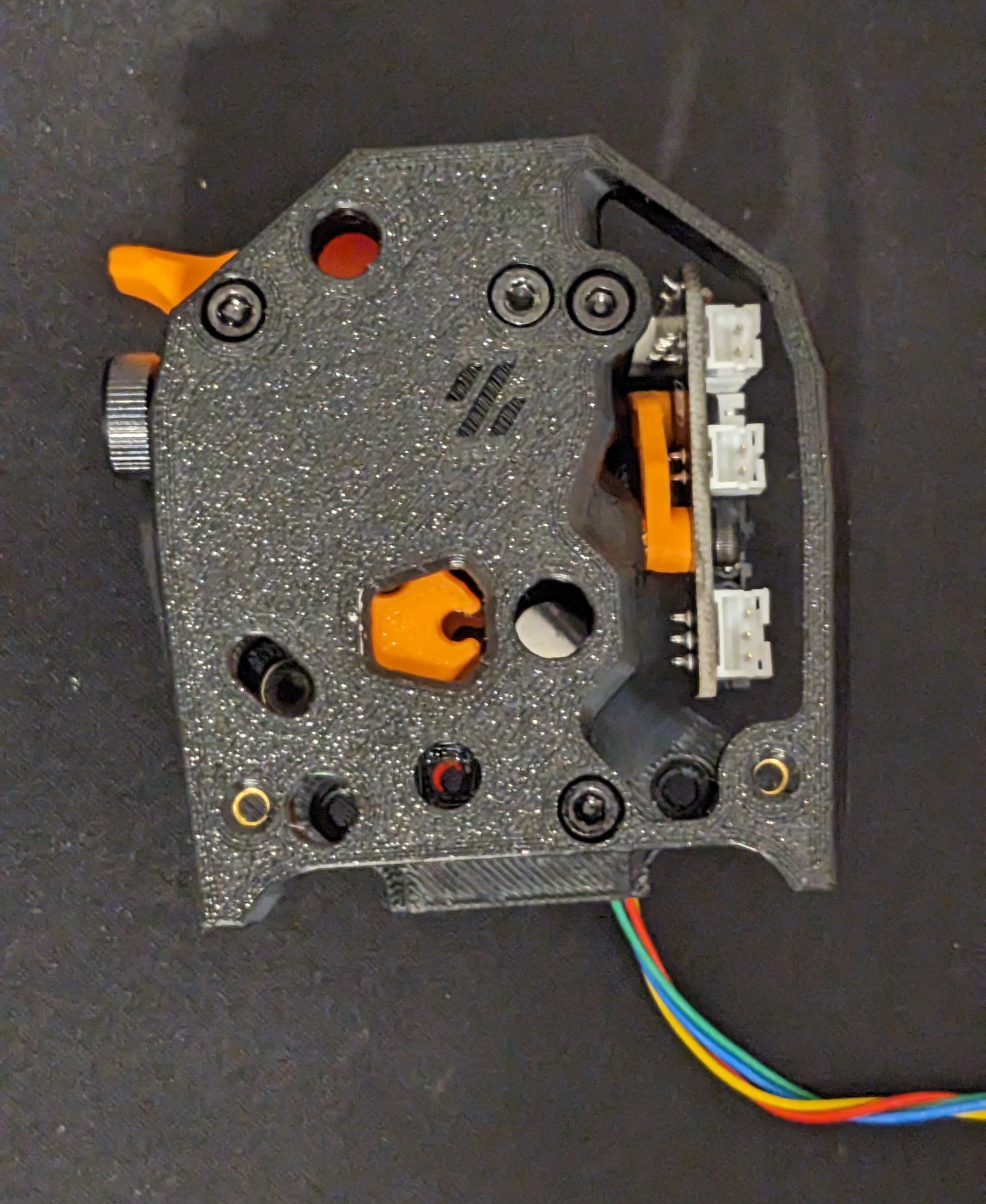
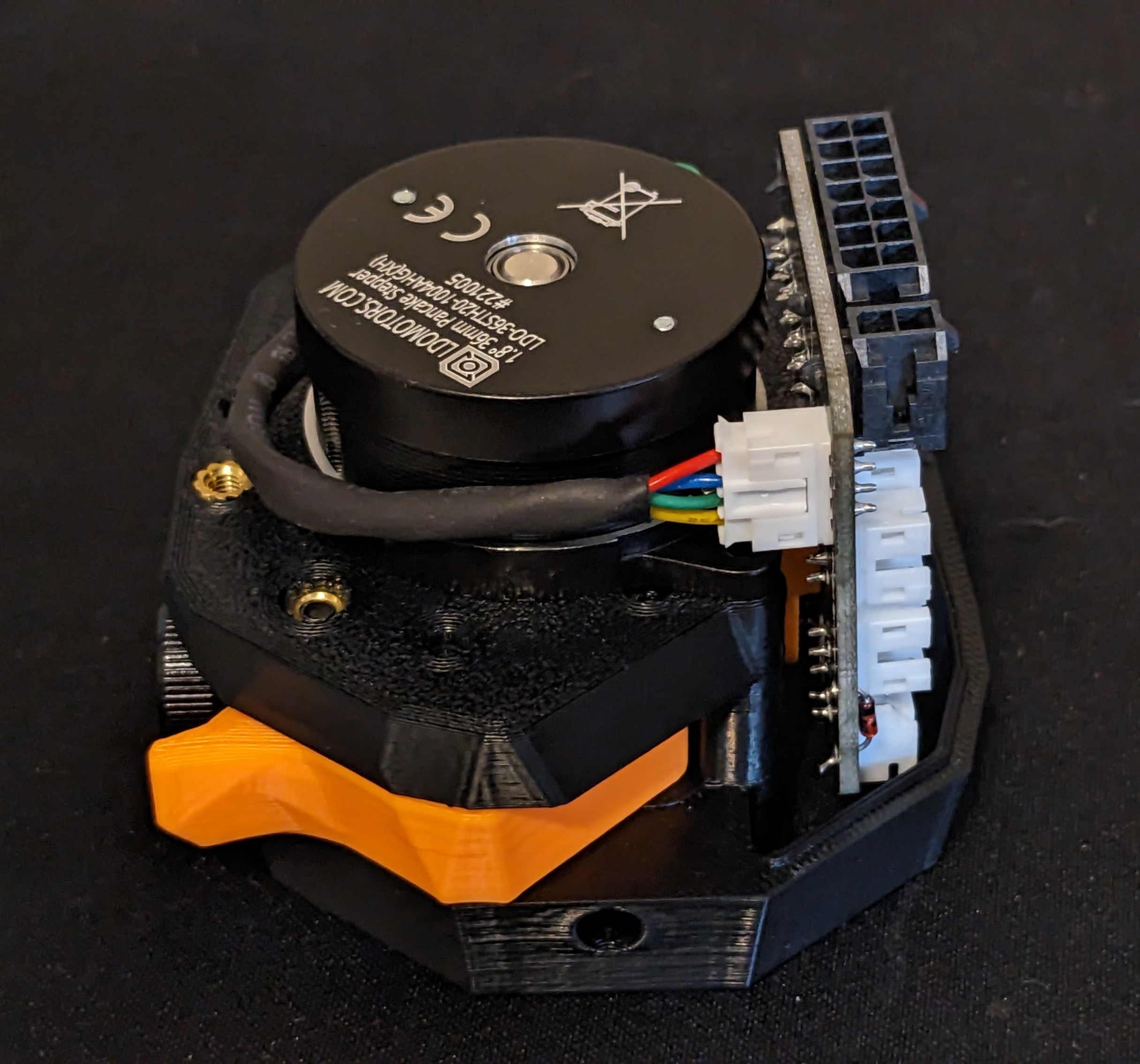
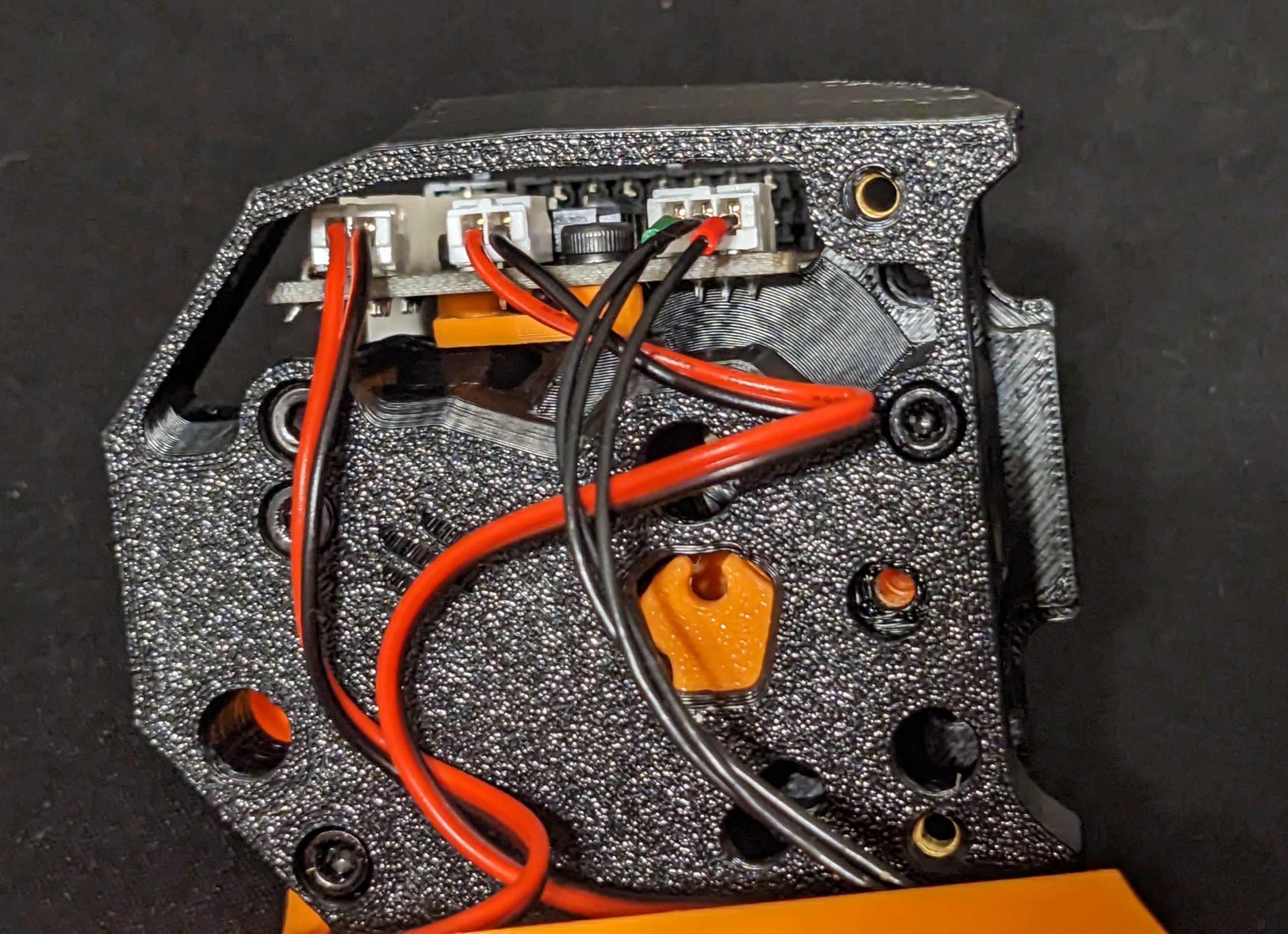
Place the PCB spacer on the back of the PCB, ensuring the raised section is facing the circuit board.
Then use the M3x8 screws to hold the PCB spacer in place, while you mount it to the CW2 body.
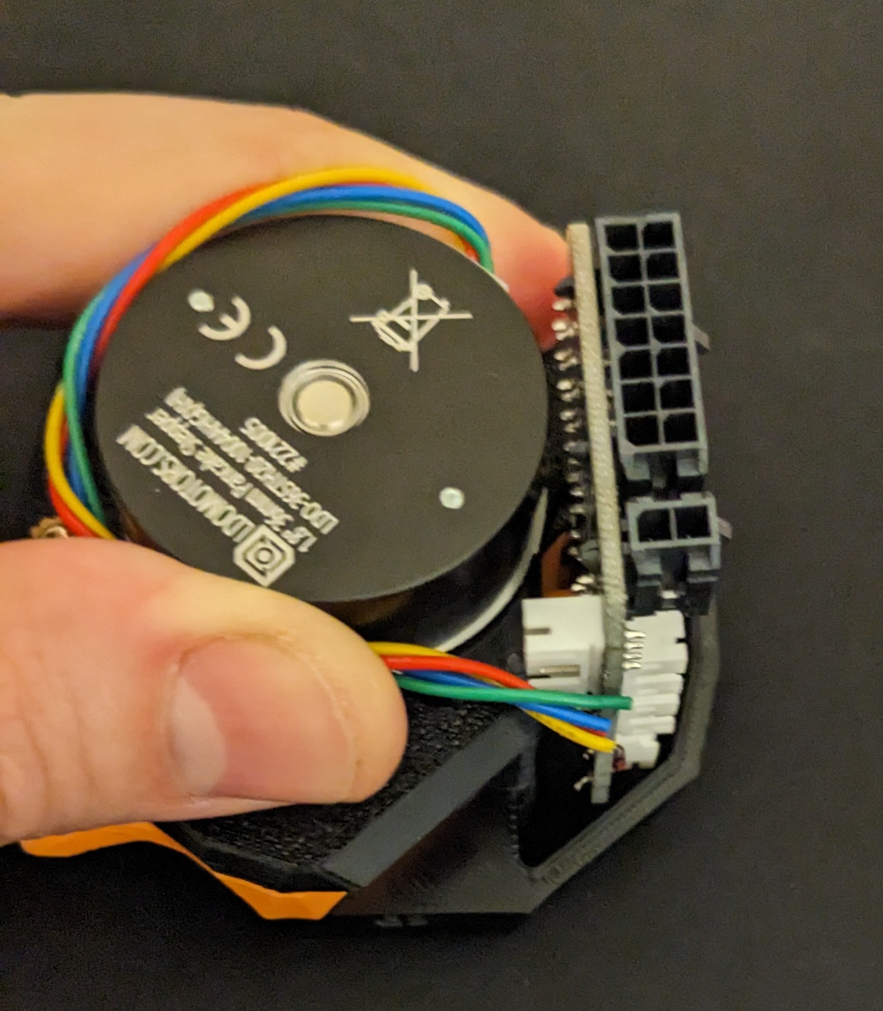
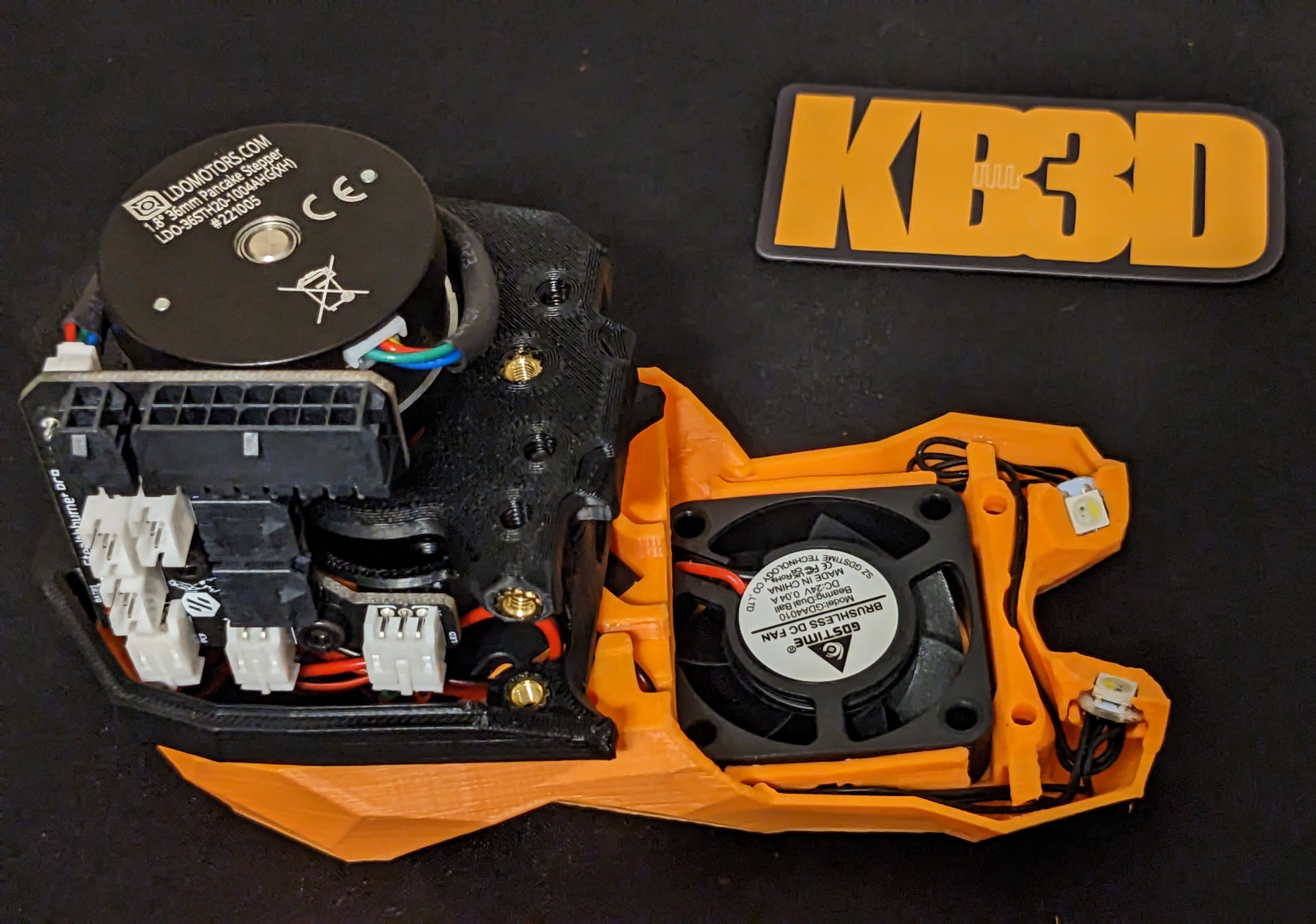
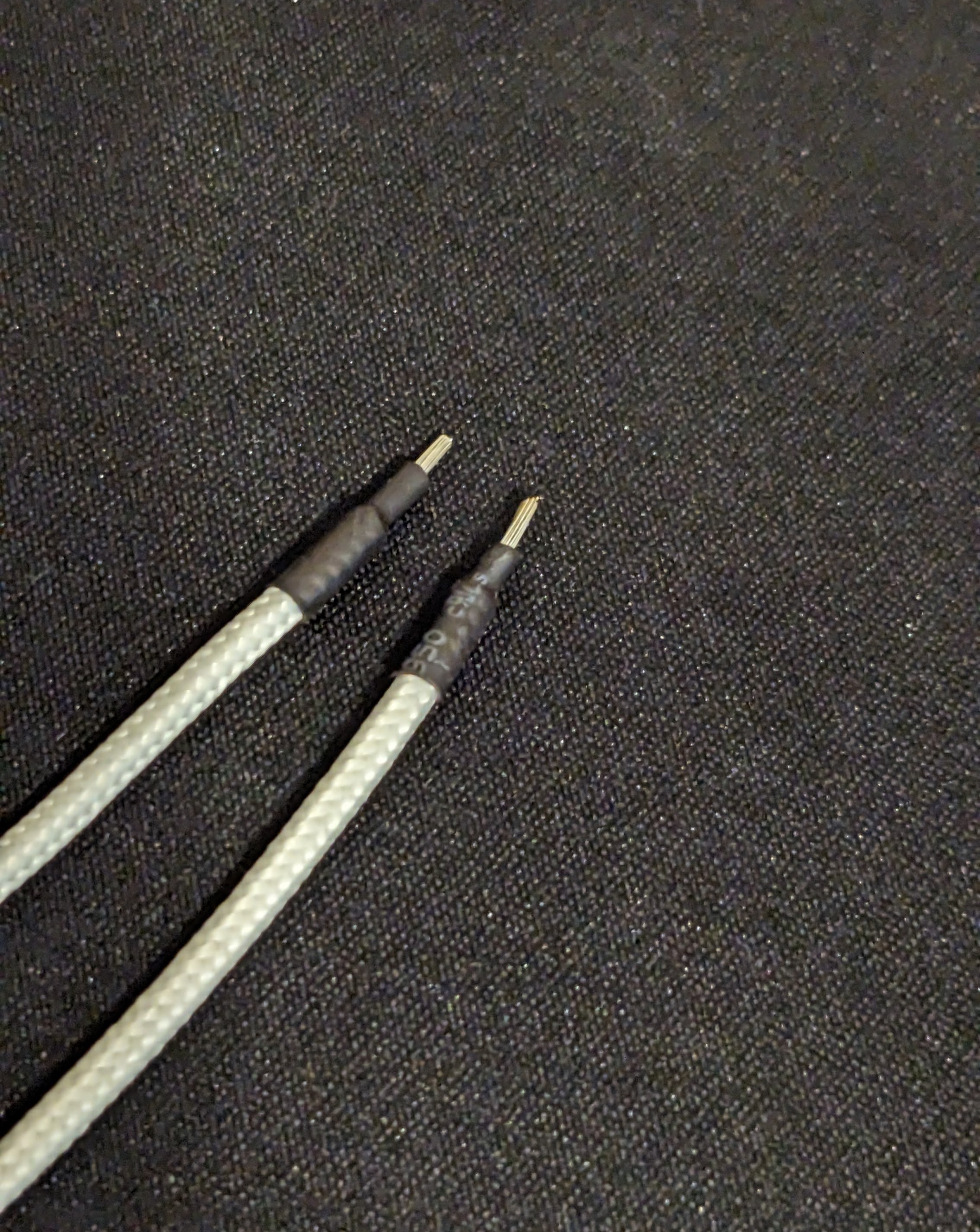
Next you will need to measure and cut the Extruder stepper motor wires.
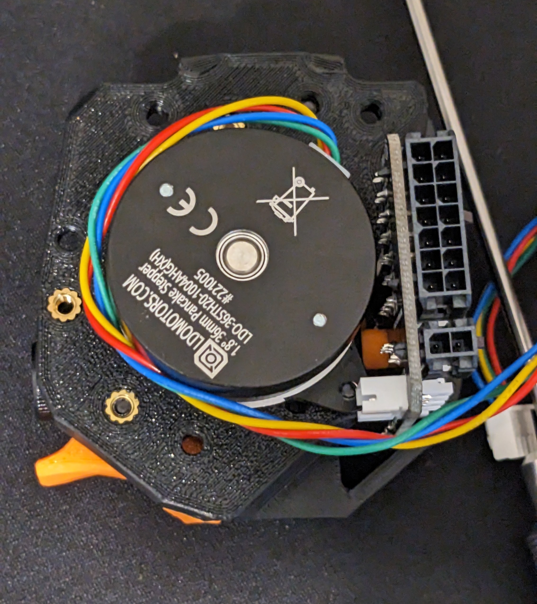
Leave a little slack, and cut the wires.
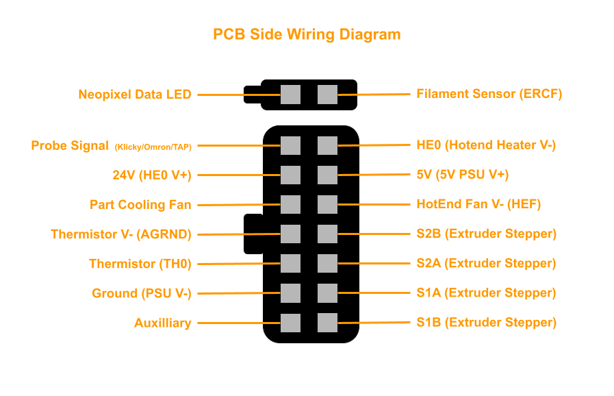
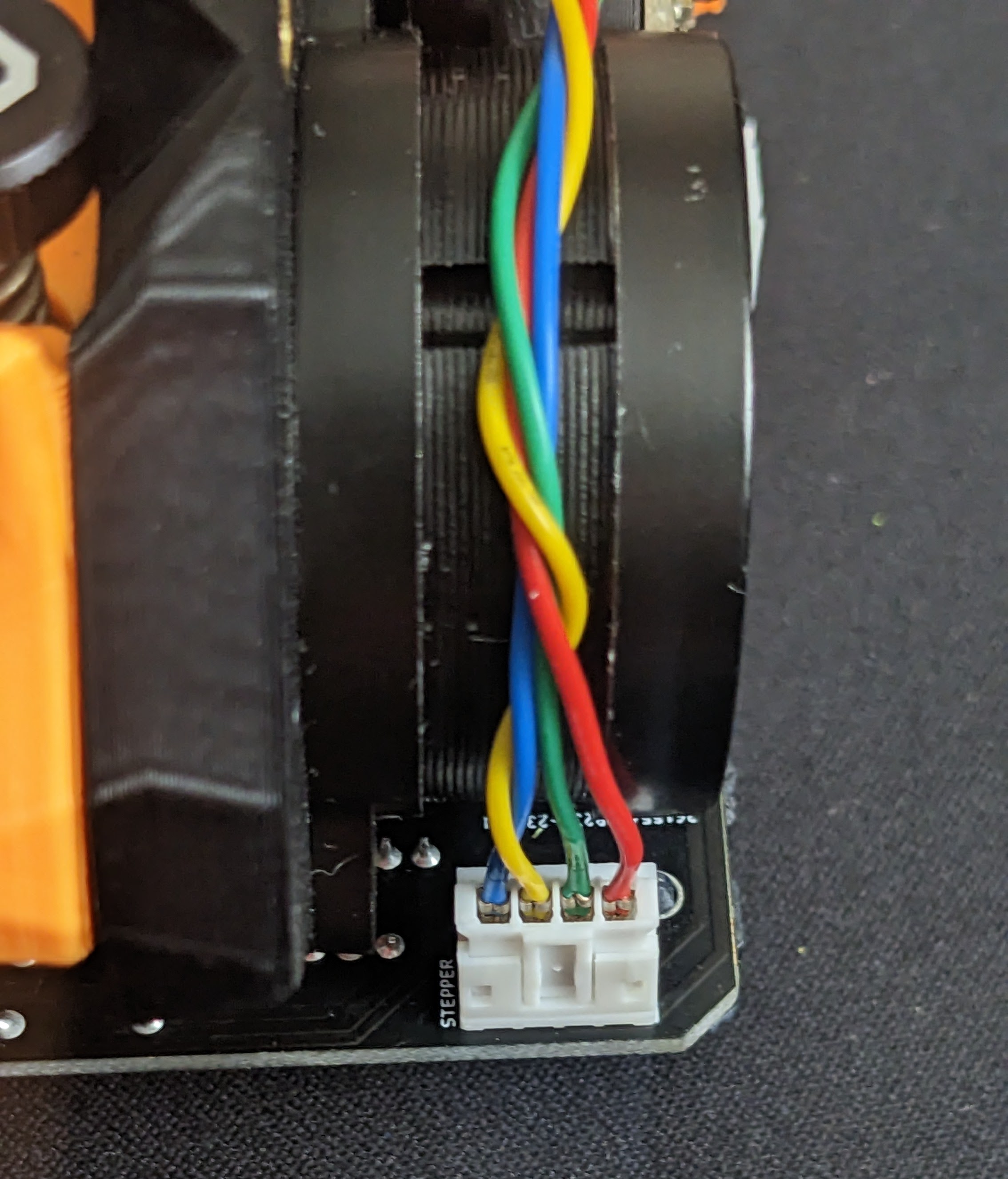
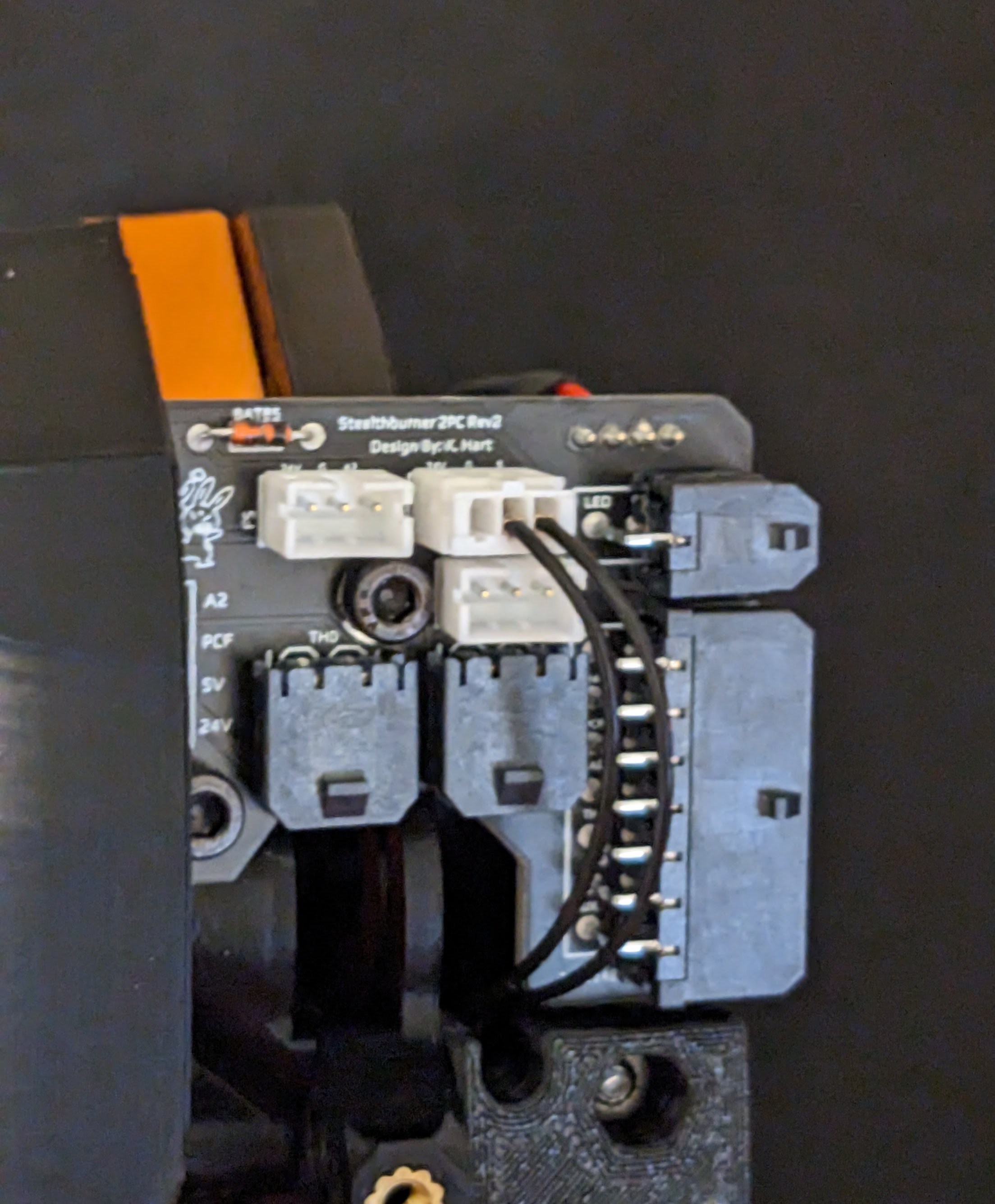
Strip the wires and install JST-PH terminals. JST-PH terminals are very small, on our Iwiss IWS-2820M, we recommend the 1.3 or 1.6 for these terminals. This guide from Digikey is very helpful. When installing the terminals in the connector, follow this image, as the pin-out is different when using the PCB.
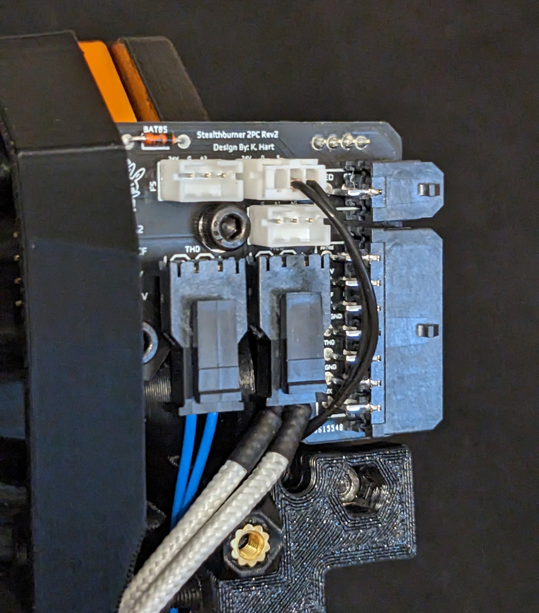
Note: The V3 and V4 have use different wiring for the Extruder motor.
V3
V4
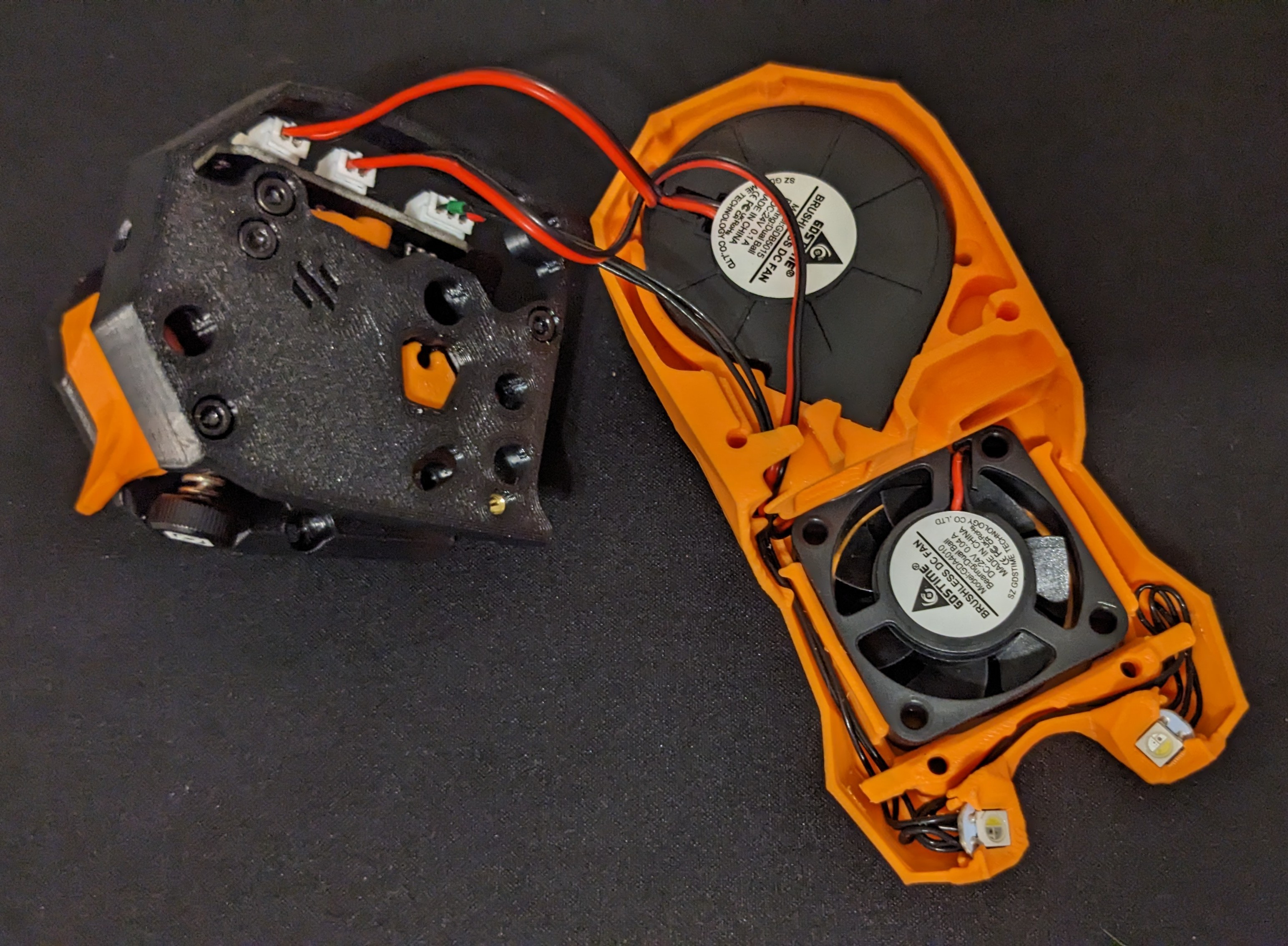
Moving to the front of the SB, you will likely need to re-terminate your fans and possibly LED's. Our Linneo Toolhead RGBW LED Harness and Rainbow Barf harness are available pre-terminated in JST-PH.
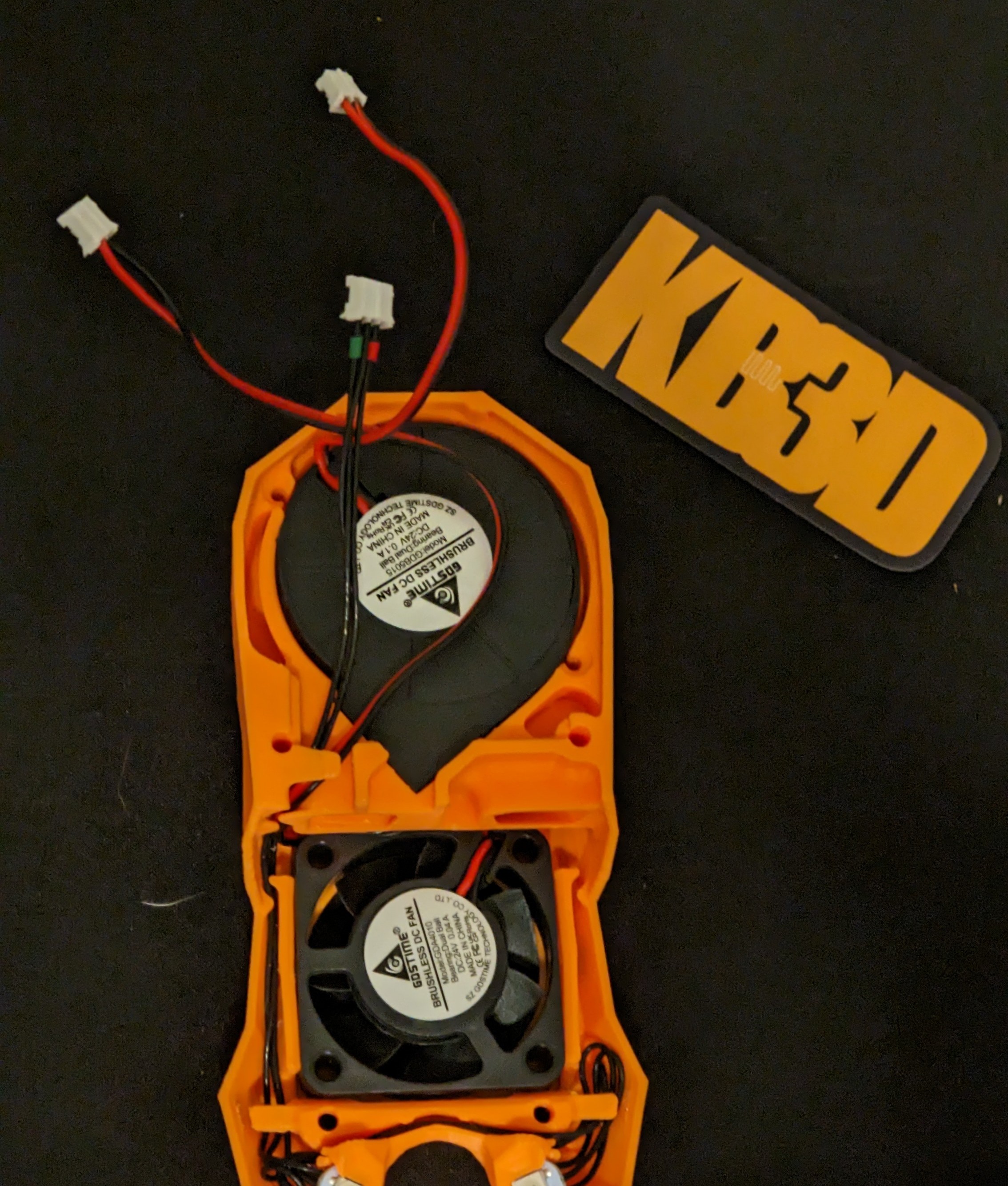
Before de-pinning or cutting the wires on your LED harness, ensure they are labeled to avoid mis-wiring.
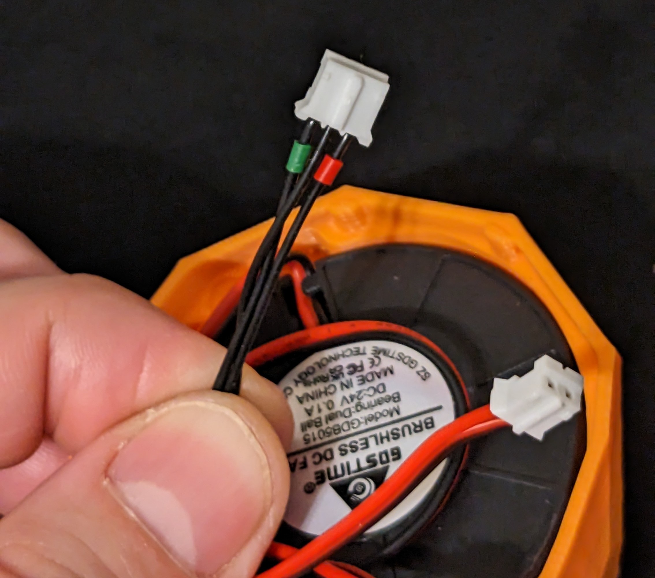
Also ensure you wire your fan's correctly, the positive wire should be on the left when looking down from the top (ie the side with the guide down the center). Leave plenty of wire slack, as you will want to be able to remove the front face to get to the connectors on the PCB. Their is room between the fan and the motor plate for the wire.
Before proceeding, double check your wiring is correct.
If you are using an Omron style inductive probe, you may need to re-terminate your probe wires with JST-PH. Again, double check your wiring to make sure you wire your probe correctly. The PCB requires 24v, Ground, Signal in that order looking at the JST connector.
Note: For the V4 version of the Toolhead PCB, you need to ensure you use the 24V Probe port for your Omron probe, which is on on the right.
For the Klicky probe, you will only need to use Signal and Ground, with the V4 board, you can use either probe port for Klicky.
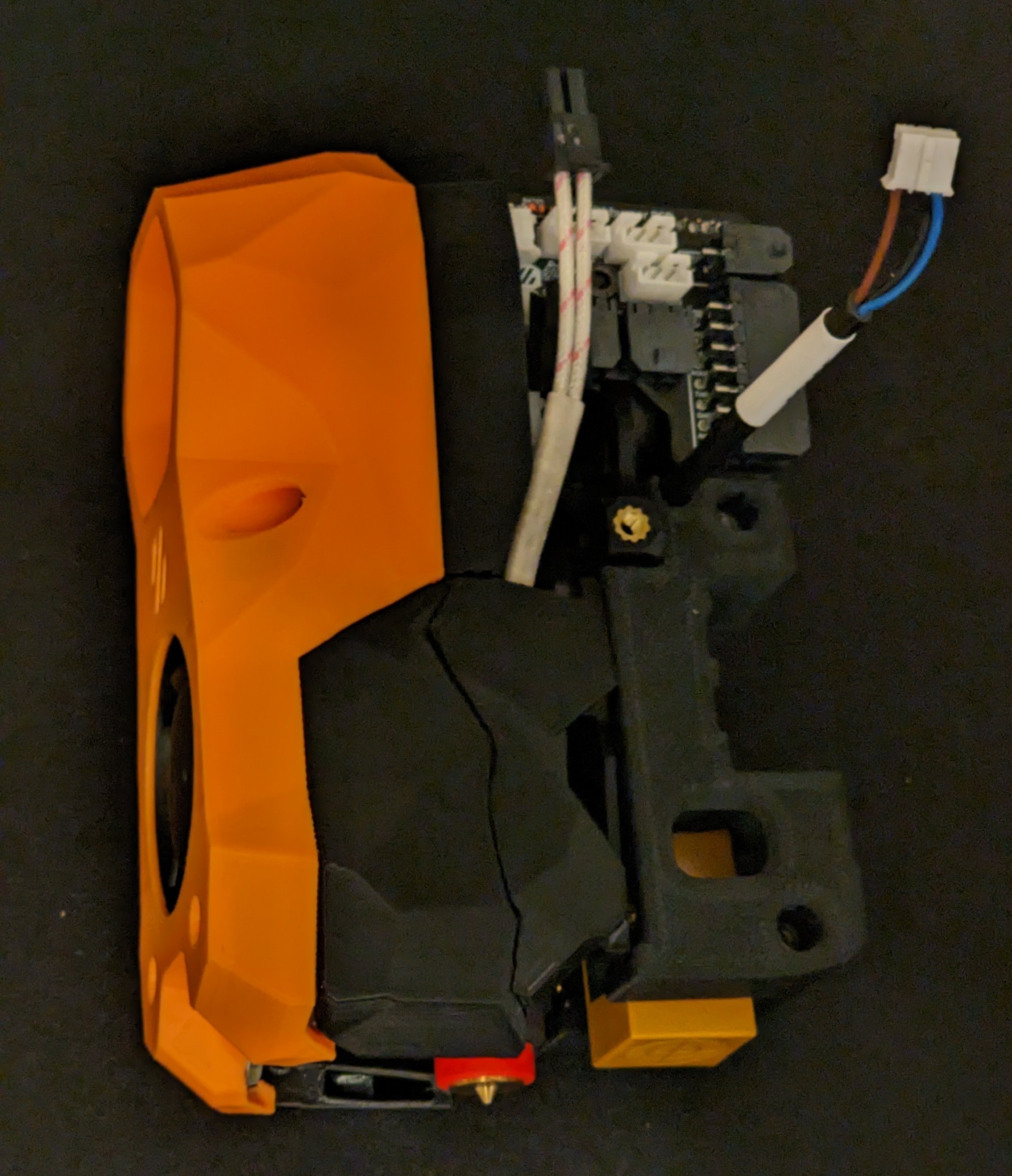
You will need to terminate your hotend heater and thermistor with 2-pin Molex Microfit 3.0 connectors (the Revo Voron come pre-terminated). Neither of these connectors are polarized (ie you don't need to ensure + / - order). When terminating heater wires, it can sometimes be easier to strip off extra insulation and use heatshrink tubing to cover the insulation and give you something more manageable to crimp on to.
This is the last of the toolhead specific wiring, for the Toolhead to MCU wiring, this guide is helpful. The pinout for the Molex connectors going to the MCU are below.