¶ Voron Afterburner PCB to Stealthburner PCB Upgrade
Here are links to the Afterburner PCB and Stealthburner PCB designs from hartk.
The Stealthburner PCB has a slightly different pin outs than it's predecessor, the Afterburner PCB. Their are also multiple variations on the AB PCB, we will cover the most common.
¶ Afterburner Toolhead PCB v4
The changes required to your wiring harness are fairly minor, with only one pin really needing to be changed on the Molex 14-pin connector (this is likely easier to change on the MCU side, rather than re-pinning the Molex connector). You will also need to run one additional wire up to the toolhead to provide the Neopixel data signal. You could re-use the X End Stop wire, but you will need to either remove the pin from the 14-pin Molex connector, or cut it and re-terminate (this does mean you wouldn't be able to add a chamber thermistor later).

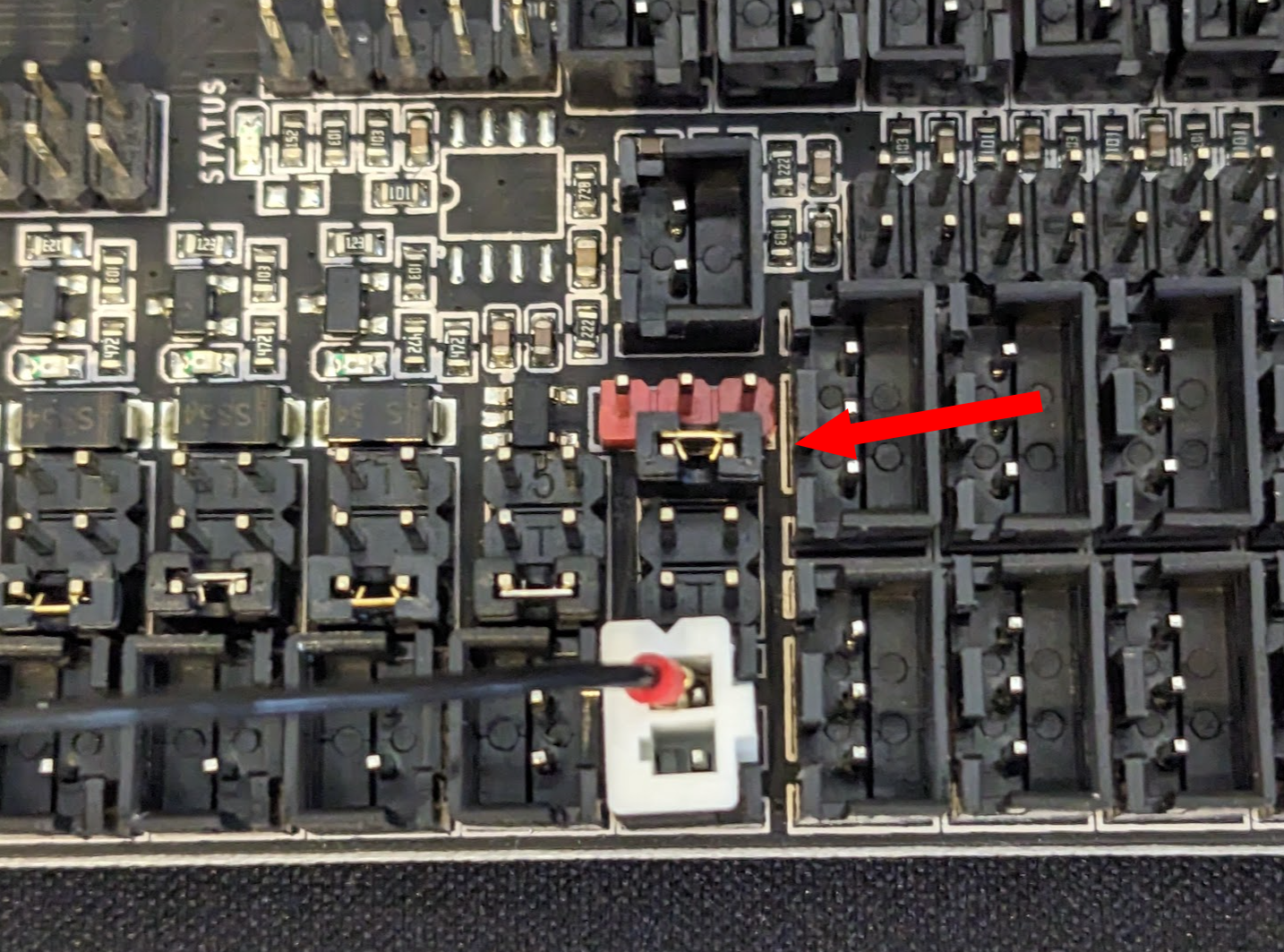
You will need to provide 5V + , which you can get from a Fan header set to 5V. On an Octopus 1.1, here is a picture using a fan header set to 5V.

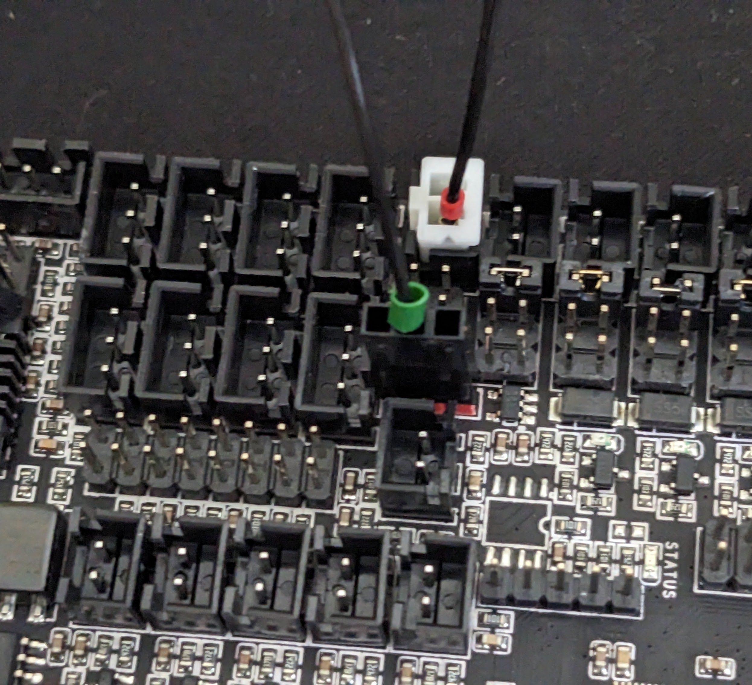
For the two pin vertical Molex connector, you likely only need to provide the Neopixel signal. It will come from the center pin of the red Dupont style connector on the Octopus.

¶ Afterburner 3.Rabbit
The changes required to your wiring harness are fairly minor, with only one pin really needing to be changed on the Molex 14-pin connector (this is likely easier to change on the MCU side, rather than re-pinning the Molex connector).

If you had populated the 2pin Molex, you will need to move the 5v supply to what was the Chamber Thermistor pin, connect the Neopixel data signal to what was the 5v supply, and move the Chamber thermistor to what was the likely unused X End Stop connector.
If you were not using the secondary 2-pin Molex connector, you can get the 5v signal from a fan header set to 5v, as pictured here with an Octopus board.

And provide the Neopixel signal from the center pin of the red Dupont style connector on the Octopus.
